
Light grid for detecting objects in a monitoring region

a technology for monitoring regions and light grids, applied in the direction of optical detection, electric variable regulation, discharge tube incandescent screens, etc., can solve the problems of no synchronization, no protection against non-permitted intrusion, and interruption of light grid operation, etc., to achieve robust operation and simple manufacturing

Inactive Publication Date: 2006-07-25
SICK AG
View PDF18 Cites 22 Cited by
  • Summary
  • Abstract
  • Description
  • Claims
  • Application Information

AI Technical Summary

Benefits of technology

[0004]It is therefore an object of the invention to provide a light grid, which permits a certain and reliable synchronization between the transmitter unit and the receiver unit in, where possible, all monitoring situations, which is robust in operation and which is simple to manufacture.
[0006]It is achieved with such an apparatus that the synchronization procedure is fully uncoupled from the transmission of the monitoring signal in the monitoring region and thus a synchronization takes place between the transmitter unit and the receiver unit which is independent of the light transmission path between the transmitter unit and the receiver unit in the monitoring region. The light guide in accordance with the invention provided separately for the transmission of the synchronization signal ensures that a reliable synchronization of the receiver unit takes place in dependence on the transmitter unit irrespective of a feed of an object into the monitoring region and irrespective of its position and movement within the monitoring region. At the same time, the transmission of the synchronization signal by means of a lead is less prone to interference such as environmental influences than in transmission by air.
[0007]A reliable protection is thus provided with the apparatus of the invention against the intrusion of non-permitted objects into the monitoring region, with a switching off of the light grid or of parts of the light grid, when an object is fed in, no longer being required. The apparatus in accordance with the invention can moreover be produced at a favorable price and is reliable and robust in operation.

Problems solved by technology

The disadvantage of this procedure is that whenever the synchronization signal is interrupted, for example by a work piece moving into the monitoring region, no synchronization can take place between the transmitter unit and the receiver unit and thus the operation of the light grid is interrupted.
It is therefore customary practice to deactivate light grids for, for example, the time of the moving in and out of an object, whereby disadvantageously no protection against non-permitted intrusion exists in this time.

Method used


Image

  • Light grid for detecting objects in a monitoring region
  • Light grid for detecting objects in a monitoring region

Examples


Embodiment Construction

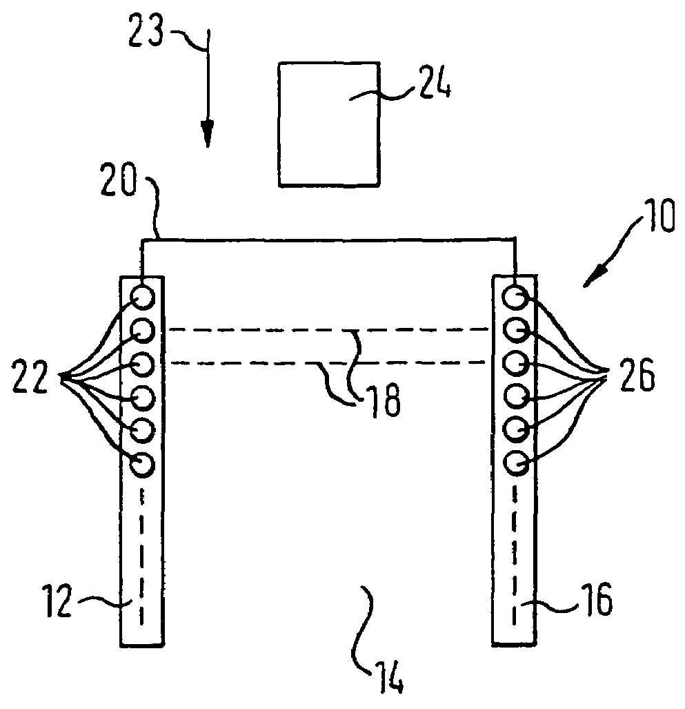
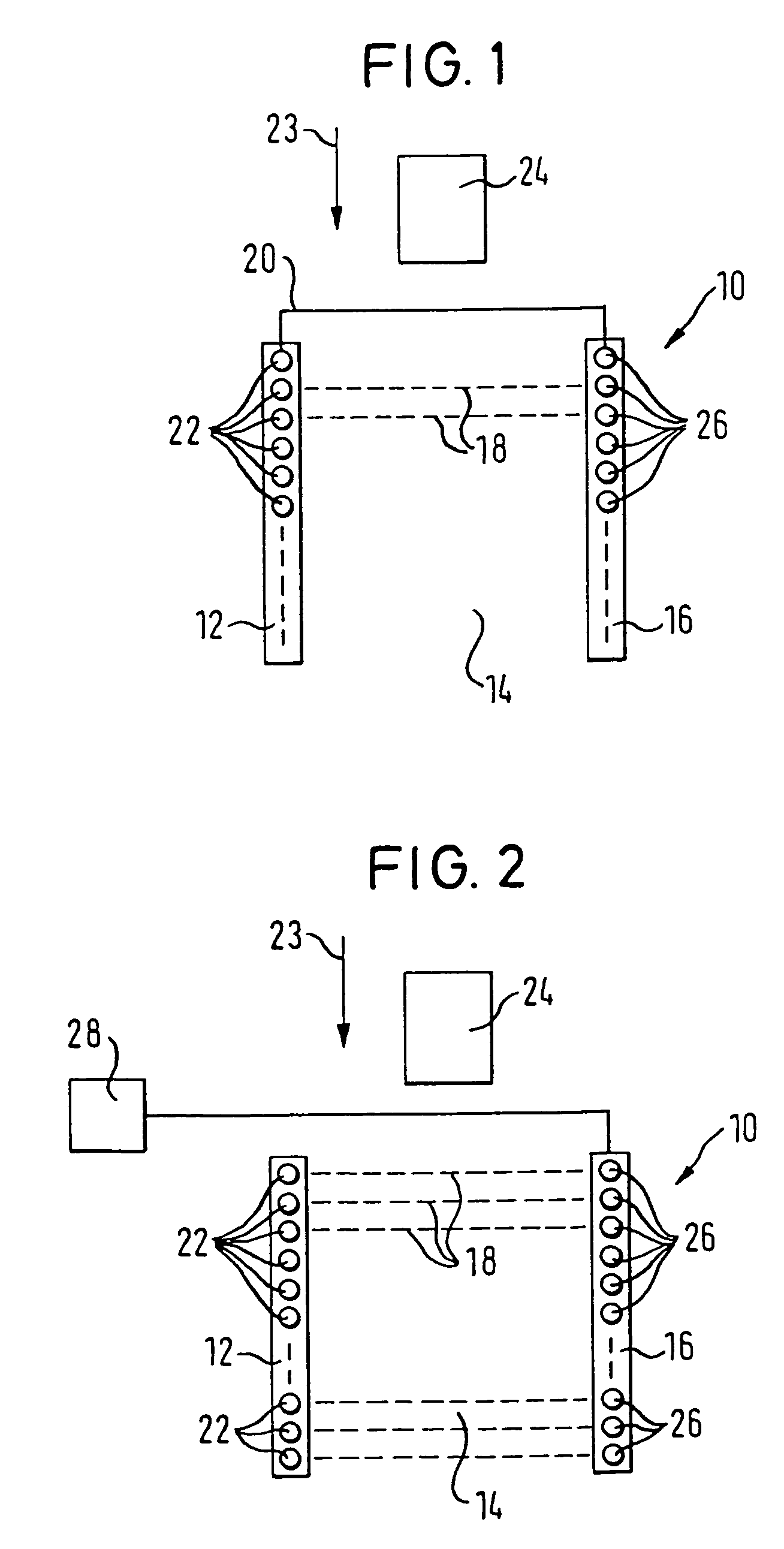
[0024]A light grid 10 is shown in FIG. 1 that comprises a transmitter unit 12 and a receiver unit 16, between which a monitoring region 14 is defined. The transmission unit 12 consists of a plurality of light transmitters 22 arranged in a row, of which, however, only six light transmitters 22 are represented. The receiver unit 16 likewise consists of a plurality of light receivers 26 arranged in a row, of which likewise only six are shown.

[0025]The transmitter unit and the receiver unit 12, 16 are arranged parallel to the floor (not shown) of a production hall, with the floor extending parallel to the plane of the drawing. The length of the transmitter unit 12 and the receiver unit 16 is dimensioned such that, for example, an unrecognized passing through of the light grid 10 by persons is not possible. An approximate length of 900 mm has proved expedient in trials.

[0026]The transmitter unit 12 and the receiver unit 16 are arranged parallel to one another at an interval of around 3 t...


PUM


Abstract

A light grid is provided for the detection of objects in a monitoring region having a transmitter unit comprising a plurality of light transmitters and a receiver unit comprising a plurality of light receivers in which respective pairs of light transmitters and light receivers associated with one another and bounding the monitoring region can be activated in succession in time in dependence on a synchronization signal transmitted between the transmitter unit and the receiver unit, with at least one light guide being provided for the transmission of the synchronization signal.

Description

BACKGROUND OF THE INVENTION[0001]The invention relates to a light grid for the detection of objects in a monitoring region having a transmitter unit comprising a plurality of light transmitters and a receiver unit comprising a plurality of light receivers in which respective pairs of light transmitters and light receivers associated with one another and bounding the monitoring region can be activated in succession in time in dependence on a synchronization signal transmitted between the transmitter unit and the receiver unit. The invention further relates to a method for the operation of such a light grid.[0002]Light grids of this kind are used, for example, in highly automated production systems in which work pieces are automatically fed, machined and taken away again. These production systems are provided as a rule with fully automatic machining centers (e.g. robot devices) and transport devices. Since the feeding, machining and taking away regions at the same time represent possi...

Claims


Application Information

Patent Timeline
IPC IPC(8): H01J1/60F16P3/14G01V8/20
CPCF16P3/14F16P3/144G01V8/20
Inventor JURS, HEINERGORNEMANN, OTTO
Owner SICK AG
Learn More