
Battery cell monitoring and balancing circuit

a battery cell and circuit technology, applied in secondary cell servicing/maintenance, instruments, electrochemical generators, etc., can solve the problems of incorrect correction measures based on such erroneous measurements, hazardous types of battery cells, and provide unreliable voltage measurements

Inactive Publication Date: 2006-07-25
O2 MICRO INT LTD
View PDF27 Cites 115 Cited by
  • Summary
  • Abstract
  • Description
  • Claims
  • Application Information

AI Technical Summary

Benefits of technology

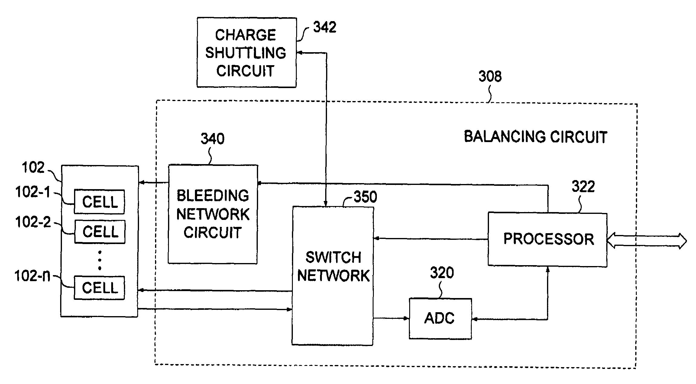
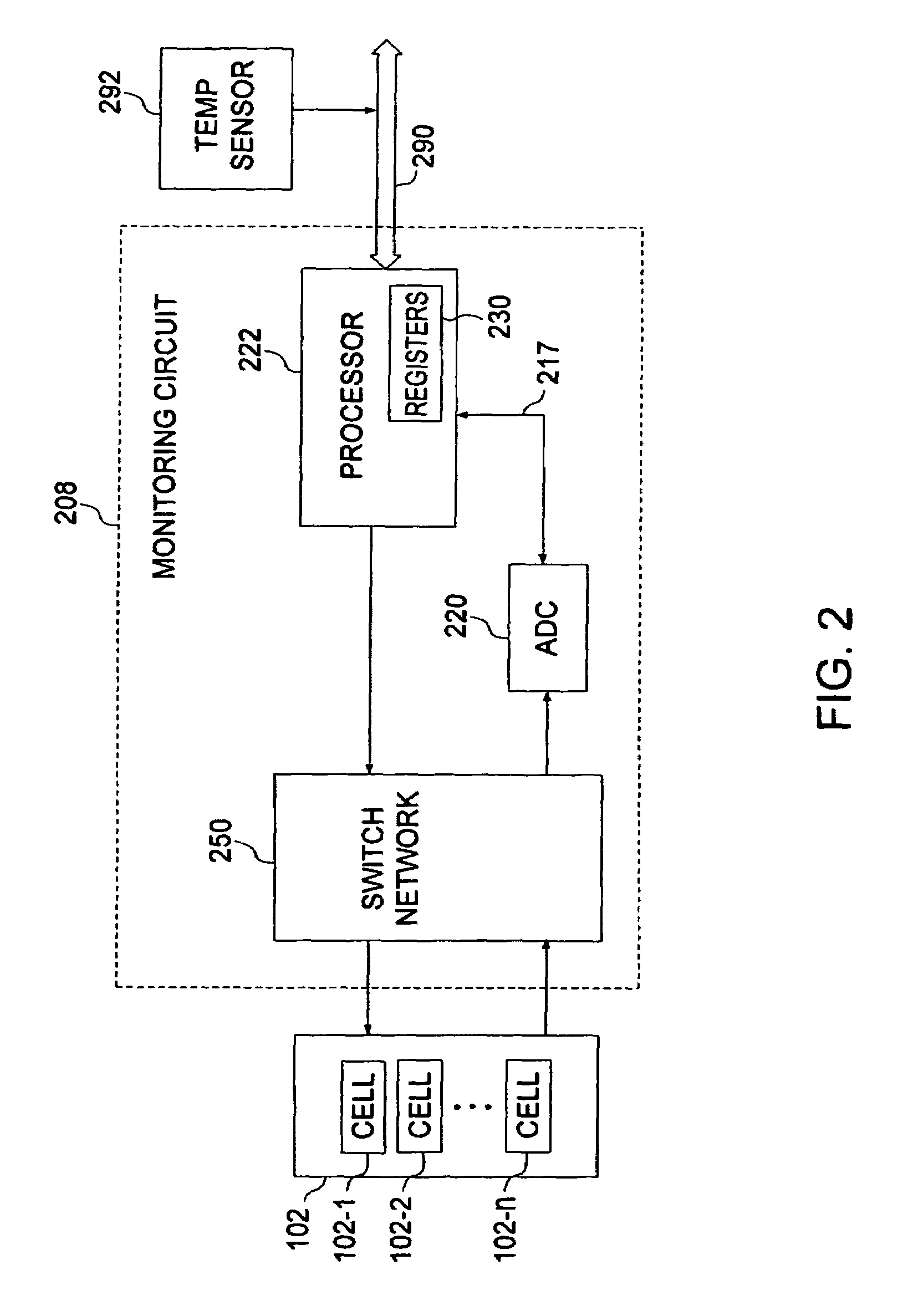
[0006]A monitoring circuit for accurately monitoring a voltage level from each of a plurality of battery cells of a battery pack consistent with the invention includes an analog to digital converter (ADC) and a processor. The ADC is configured to accept an analog voltage signal from each of the plurality of battery cells and convert each analog voltage signal to a digital signal representative of a voltage level of each battery cell. The processor is configured to receive each digital signal and to provide a safety alert signal based on at least one of the digital signals.

Problems solved by technology

Certain types of battery cells, e.g., lithium ion cells, can be hazardous if charged significantly above its normal charge range or discharged below its normal charge range.
There are several drawbacks to such an arrangement.
First, such an arrangement may provide for unreliable voltage measurements.
As such, corrective measures may be incorrectly taken based on such erroneous measurements.
Second, the threshold levels such as over voltage and under voltage are not easily adjustable.
This is an issue since different battery pack types and different manufacturers for the same battery pack type may require different over and under voltage thresholds.
Third, when the cells in one battery pack are unbalanced (e.g., after many charging and discharging cycles) a traditional bleeding method can be undertaken to balance the cell.
However, a bleeding decision is typically made only when the battery is near fully charged at the time of charging.
Since bleeding current is typically limited in order to avoid excessive heat generation, bleeding takes a certain time interval.
If more than one cell needs to be bled, there is simply not enough time in one charge cycle to accomplish this task.

Method used


Image

  • Battery cell monitoring and balancing circuit
  • Battery cell monitoring and balancing circuit
  • Battery cell monitoring and balancing circuit

Examples


Embodiment Construction

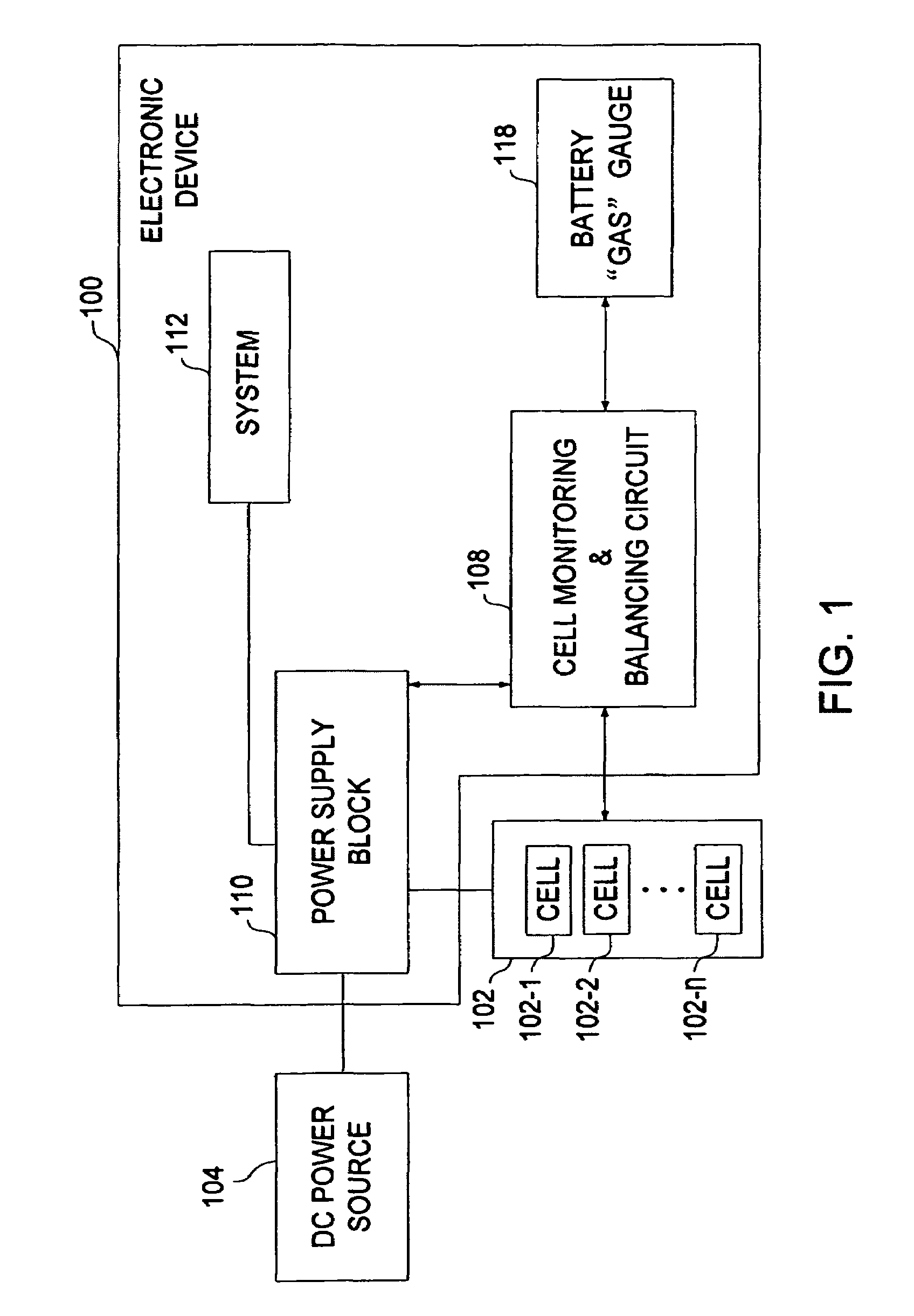
[0019]Turning to FIG. 1, a simplified block diagram of an electronic device 100 capable of being powered from a battery pack 102 or a DC power source 104 is illustrated. The battery pack 102 may containing a plurality of battery cells 102-1, 102-2, 102-n. The cell types may be of various rechargeable types known in the art such as lithium-ion, nickel-cadmium, nickel-metal hydride batteries, or the like.

[0020]If the electronic device 100 is a laptop computer it would include a variety of components known to those skilled in the art which are not illustrated in FIG. 1. For example, the laptop may include an input device for inputting data to the laptop, a central processing unit (CPU) or processor, for example a Pentium processor available from Intel Corporation, for executing instructions and controlling operation of the laptop, and an output device, e.g., a LCD or speakers, for outputting data from the laptop.

[0021]To recharge the battery pack 102 and / or supply power to the system 1...


PUM

PropertyMeasurementUnit
voltageaaaaaaaaaa
voltageaaaaaaaaaa
voltage levelaaaaaaaaaa

Abstract

A monitoring circuit for accurately monitoring a voltage level from each of a plurality of battery cells of a battery pack includes an analog to digital converter (ADC) and a processor. The ADC is configured to accept an analog voltage signal from each of the plurality of battery cells and convert each analog voltage signal to a digital signal representative of an accurate voltage level of each battery cell. The processor receives such signals and provides a safety alert signal based on at least one of the signals. The ADC resolution may be adjustable. A balancing circuit provides a balancing signal if at least two of the digital signals indicate a voltage difference between two cells is greater than a battery cell balance threshold. An electronic device including such monitoring and balancing circuits is also provided. Various methods are also provided.

Description

FIELD OF THE INVENTION[0001]The present invention relates to a battery cell monitoring and balancing circuit, and in particular to such a circuit that directly digitizes analog battery cell voltage levels into associated digital signals.BACKGROUND OF THE INVENTION[0002]Multi-cell rechargeable batteries are utilized in a variety of applications given their higher voltage delivery and greater capacity. Such applications include, but are not limited to, electronic devices such as laptops, cellular phones, personal digital assistants, and the like. Certain types of battery cells, e.g., lithium ion cells, can be hazardous if charged significantly above its normal charge range or discharged below its normal charge range. As such, a typical monitoring and protection circuit may utilize a switch network to transfer voltage charges to a capacitor. Voltage on the capacitor then represents the battery cell voltage and may then be provided to a plurality of comparators for comparing the voltage...

Claims


Application Information

Patent Timeline
Patent Type & Authority Patents(United States)
IPC IPC(8): H02J7/00G01R31/36G06F1/26G06F1/28H01M10/44H01M10/48H02J7/02H02J7/34
CPCH01M10/441H02J7/0018Y02E60/12Y02E60/10H01M10/44
Inventor LIU, LIUSHENGLI, GUOXING
Owner O2 MICRO INT LTD
Learn More