
Reception antenna of tire pressure monitoring system using radiating leakage coaxial cable

a technology of coaxial cable and antenna, which is applied in the direction of inflated body pressure measurement, near-field systems using receivers, instruments, etc., can solve the problems of increasing economic load, deformation or corrosion, and monopole antennas b>5/b> and b>5/b>′ cannot meet standard criteria, so as to improve the reception sensitivity of measured data, reduce the deviation between data measured at respective tires, and increase the reliability of data measurement

Inactive Publication Date: 2006-07-25
HYUNDAI AUTONET
View PDF6 Cites 2 Cited by
  • Summary
  • Abstract
  • Description
  • Claims
  • Application Information

AI Technical Summary

Benefits of technology

"The present invention provides a tire pressure monitoring system with a reception antenna that can be positioned anywhere in the tire to improve the reception of temperature and pressure data measured by a sensor in the tire and transmitted wirelessly. The antenna is connected to a receiver using a cable-type antenna that can be easily mounted at different positions and is not affected by the size or design of the automobile. The antenna is also coated with a covering material that protects it from environmental factors and physical impacts, increasing its lifespan. The system includes a sensor, a transmitter, a receiver, and a display unit for displaying the measured data on a screen for easy monitoring by a driver. Overall, the invention improves the reliability and stability of the tire pressure monitoring system."

Problems solved by technology

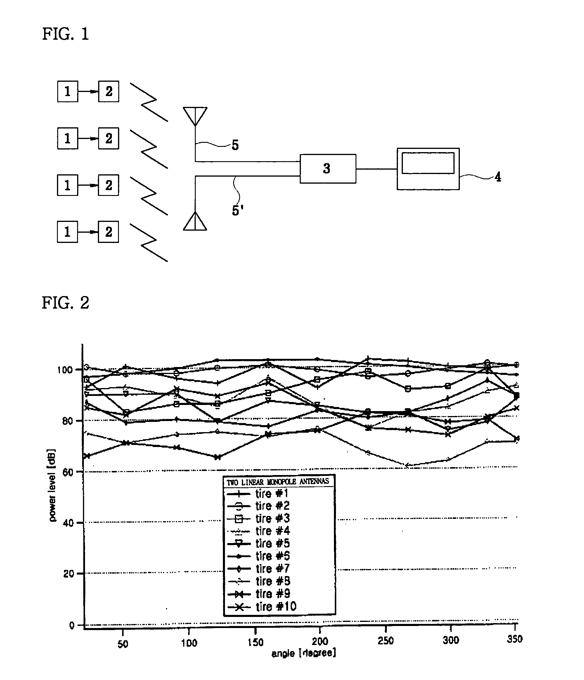
Therefore, in the prior art, the reception sensitivities of the monopole antennas 5 and 5′ differ according to the constructions, sizes and designs of automobiles as well as the materials thereof, so that the monopole antennas 5 and 5′ cannot satisfy standard criteria.
However, the above method is problematic in that, as the size of an automobile and the number of tires are increased, great efforts are required to estimate the optimal positions of the monopole antennas 5 and 5′, thus increasing the economic load due to the increased number of the monopole antennas.
Moreover, the above method is disadvantageous in that, since metal parts of the monopole antennas 5 and 5′ are consistently exposed to external environments, the monopole antennas 5 and 5′ are easily deformed or corroded due to the external factors, such as moisture and dust, as well as external physical impacts, thus the lifespan of the antennas is shortened.
For example, if the reception sensitivities of λ / 4 monopole antennas are measured after the monopole antennas are applied to a truck equipped with 10 tires, it can be seen that the reception sensitivities for data measured at the monopole antennas are remarkably decreased, and deviations between measured data respectively obtained from the 10 tires are excessively increased due to the decrease of the reception sensitivities, as shown in FIG. 2.

Method used


Image

  • Reception antenna of tire pressure monitoring system using radiating leakage coaxial cable
  • Reception antenna of tire pressure monitoring system using radiating leakage coaxial cable
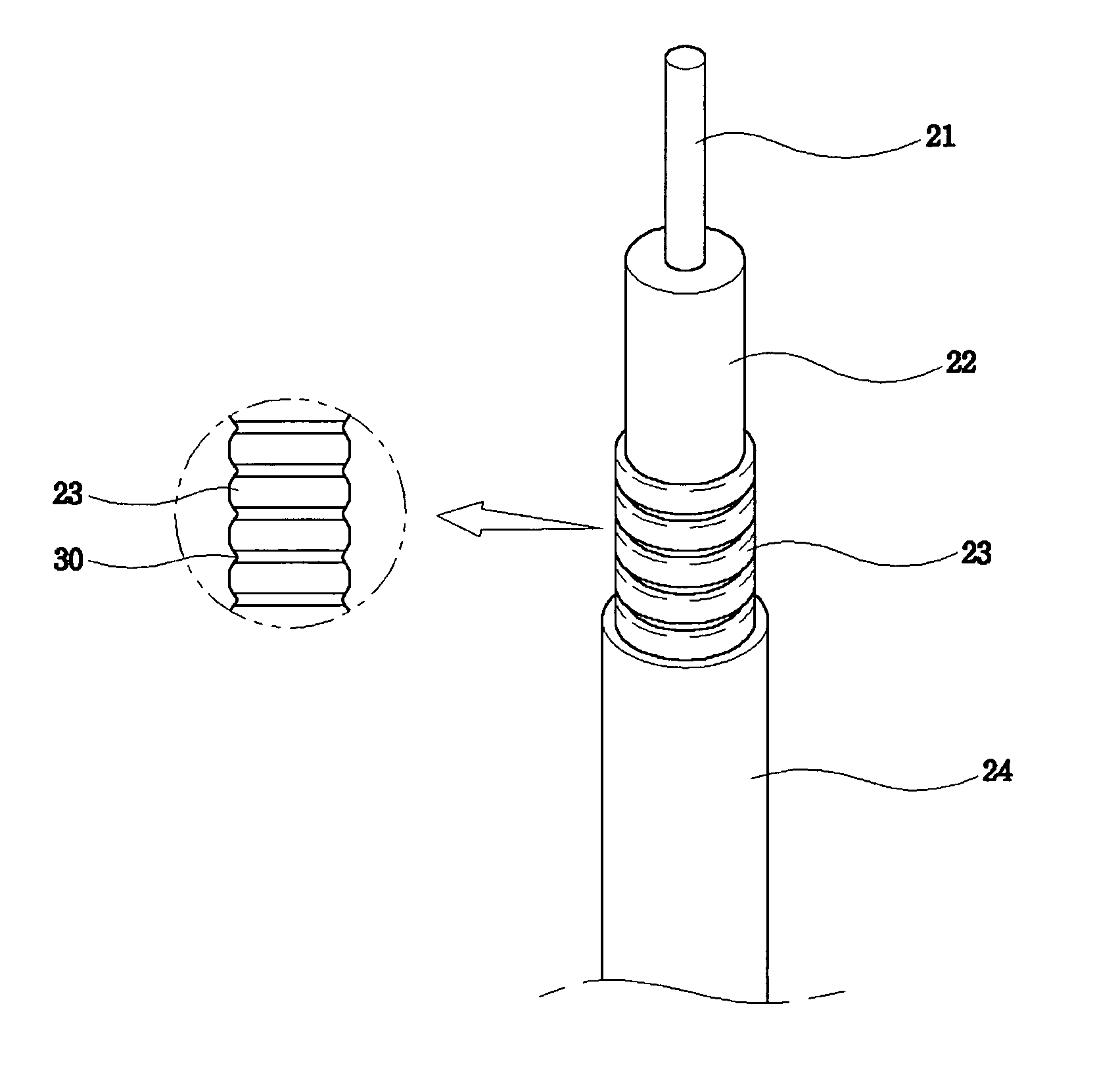
  • Reception antenna of tire pressure monitoring system using radiating leakage coaxial cable

Examples


Embodiment Construction

[0025]Hereinafter, embodiments of the present invention will be described in detail with reference to the attached drawings.

[0026]Reference now should be made to the drawings, in which the same reference numerals are used throughout the different drawings to designate the same or similar components.

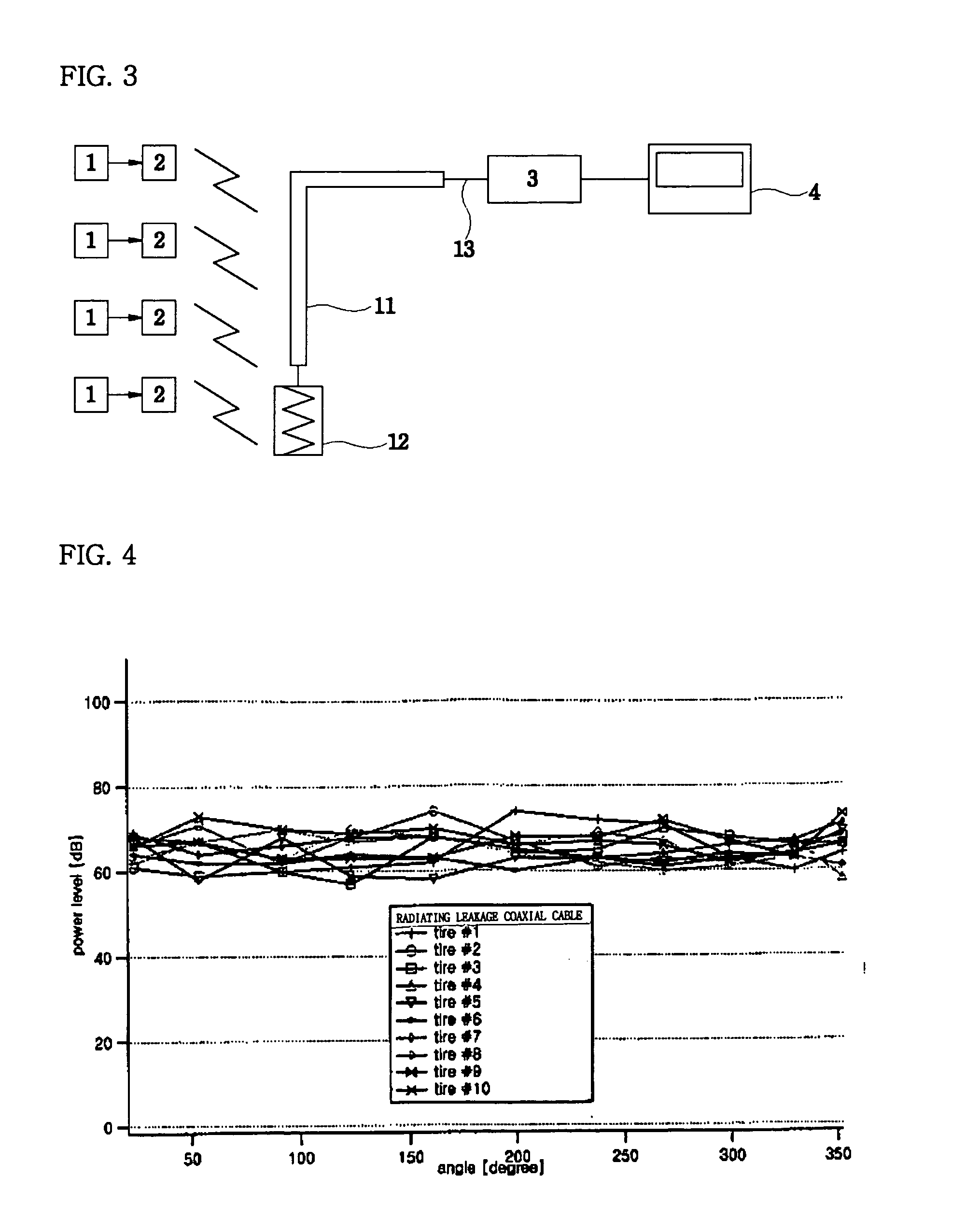
[0027]FIG. 3 is a view showing the construction of a tire pressure monitoring system using a reception antenna implemented by a radiating leakage coaxial cable according to an embodiment of the present invention, and FIG. 5 is a view showing the status of a transmitter, having a sensor therein, mounted on a vehicle wheel according to an embodiment of the present invention.

[0028]FIG. 6 is a view showing the construction of an antenna having grooves formed at regular intervals on a corrugated conductor surrounding a dielectric according to another embodiment of the present invention, and FIG. 7 is a view showing the construction of an antenna having alternately-arranged slots formed in a co...


PUM

PropertyMeasurementUnit
termination impedanceaaaaaaaaaa
impedanceaaaaaaaaaa
temperatureaaaaaaaaaa

Abstract

The present invention relates to a reception antenna structure of a tire pressure monitoring system. The reception antenna is implemented using a cable-type antenna connected to a receiver of the tire pressure monitoring system. The cable-type antenna enables a mounting position of the antenna to be freely changed and improves a reception rate for measured data about temperature and pressure of a tire, that is modulated into data in the UHF band and transmitted to the outside of the tire in a wireless manner by a transmitter. According to the present invention, the reception antenna of a tire pressure monitoring system is implemented using a radiating leakage coaxial cable so as to enable the position of the antenna to be freely changed, so that, when tire pressure data is measured by a temperature and pressure sensor included in the transmitter within the tire and then transmitted through a tire pressure monitoring transmitter in a wireless manner, the reception sensitivity for the measured data is improved, thus increasing the reliability of the data measured at the tire, and guaranteeing the stability of the tire on the basis of the reliability of the reception sensitivity for the measured data.

Description

BACKGROUND OF THE INVENTION[0001]1. Field of the Invention[0002]The present invention relates, in general, to a reception antenna structure of a tire pressure monitoring system and, more particularly, to a reception antenna of a tire pressure monitoring system using a radiating leakage coaxial cable, in which the reception antenna of the tire pressure monitoring system is implemented using the radiating leakage coaxial cable, thus further improving reception performance for measured data transmitted in a wireless manner, when a transmitter transmits tire pressure data measured by a temperature and pressure sensor included in the transmitter within a tire in a wireless manner. Korean application number 10-2003-0075734 filed Oct. 29, 2003 is hereby incorporated by reference.[0003]2. Description of the Related Art[0004]As well known to those skilled in the art, a tire pressure monitoring system (TPMS) used in automobiles includes a sensor 1 for measuring the internal temperature and pr...

Claims


Application Information

Patent Timeline
Patent Type & Authority Patents(United States)
IPC IPC(8): H01Q1/36G01L17/00B60C23/02B60C23/04B60C23/20G08C17/02H01Q1/22H01Q13/20H01Q13/22H04B5/48
CPCB60C23/0408H01Q13/203H01Q1/2241H01Q1/22B60C23/04985H04B5/48
Inventor CHOI, SANG HOONCHUN, DONG PILKWON, DAE HYUKNA, HEU KYONGKIM, SANG KOOKCHO, HANG KEELEE, WON JO
Owner HYUNDAI AUTONET
Learn More