Flutter test model

a test model and airflow technology, applied in the field of flutter test models, can solve the problems of preventing the accurate flutter test from being carried out, affecting the accuracy of the test, etc., and achieve the effect of preventing airflow disturban

Active Publication Date: 2006-07-25
AMERICAN HONDA MOTOR COMPANY
View PDF7 Cites 7 Cited by
  • Summary
  • Abstract
  • Description
  • Claims
  • Application Information

AI Technical Summary

Benefits of technology

[0007]The present invention has been conducted under the above-mentioned circumstances, and it is an object of the present invention to prevent airflow disturbance caused by fixing means for fixing a wing element to an elastic spar in a flutter test model.
[0009]In accordance with the above-mentioned arrangement, since the connecting means for connecting the wing element to the elastic spar is disposed within the wing element, the connecting means is not exposed on the surface of the test wing, and when a flutter test is carried out in a wind tunnel the airflow over the surface of the test wing is not disturbed by the connecting means, thereby enhancing the accuracy of the flutter test.
[0011]In accordance with the above-mentioned arrangement, since the wing element is fitted from the wing tip side around the elastic spar and the anchor member fixed to the elastic spar, and the wing element is fastened to the anchor member by means of a bolt that is inserted from the wing tip side, the anchor member and the bolt are not exposed on the surface of the test wing, thereby easily and reliably fixing the wing element to the elastic spar.

Problems solved by technology

However, fixing a wing element to an elastic spar by means of a bolt has the problem that the top of the bolt projects above the surface of the wing element, thereby disturbing the airflow and preventing an accurate flutter test from being carried out.
Even when a hole is formed on the surface of the main wing and the top of the bolt is sunk within the hole, there is still the problem that, since the hole disturbs the airflow over the surface of the main wing, an accurate flutter test is prevented.

Method used


Image

  • Flutter test model
  • Flutter test model
  • Flutter test model

Examples


Embodiment Construction

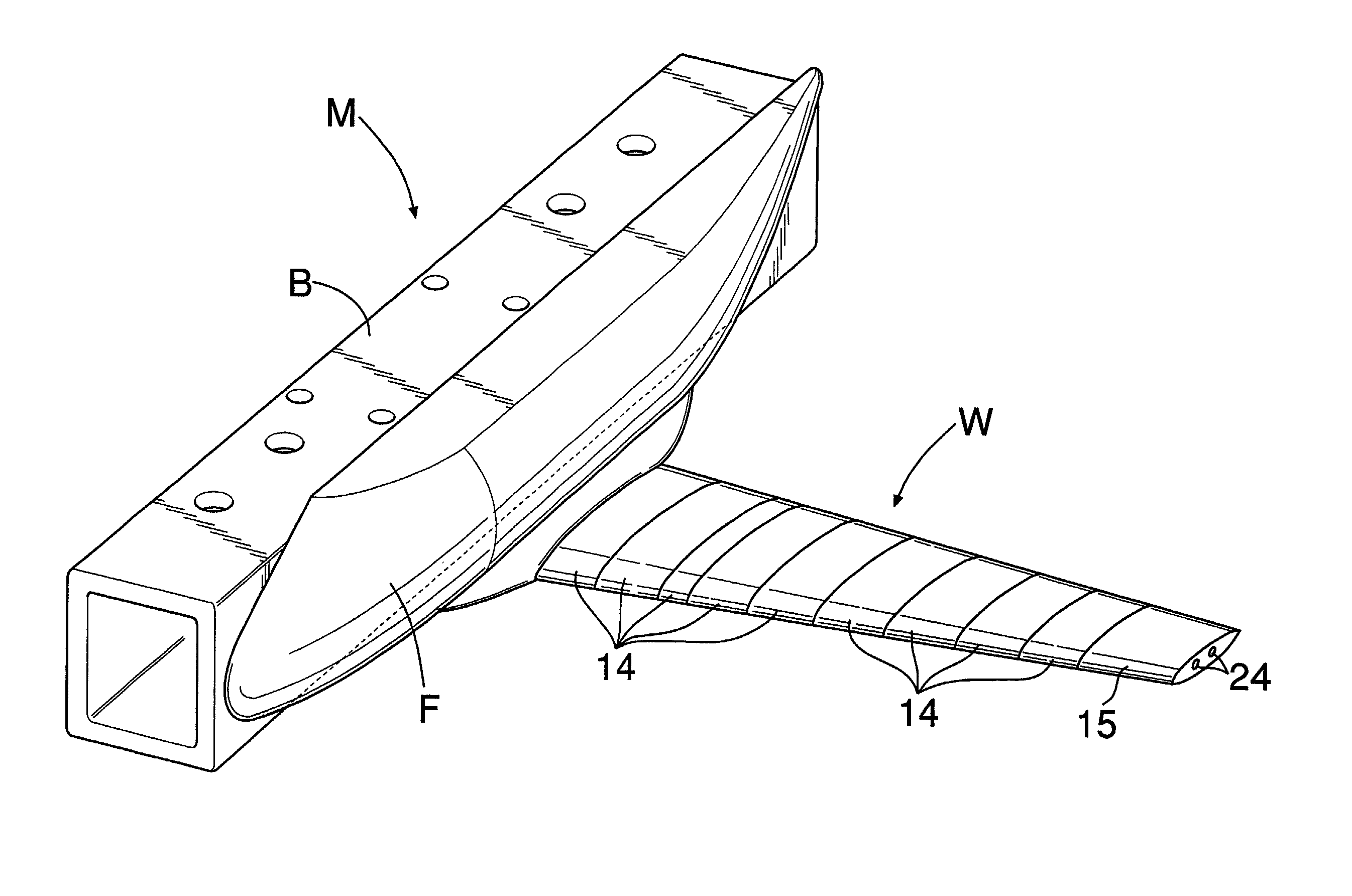
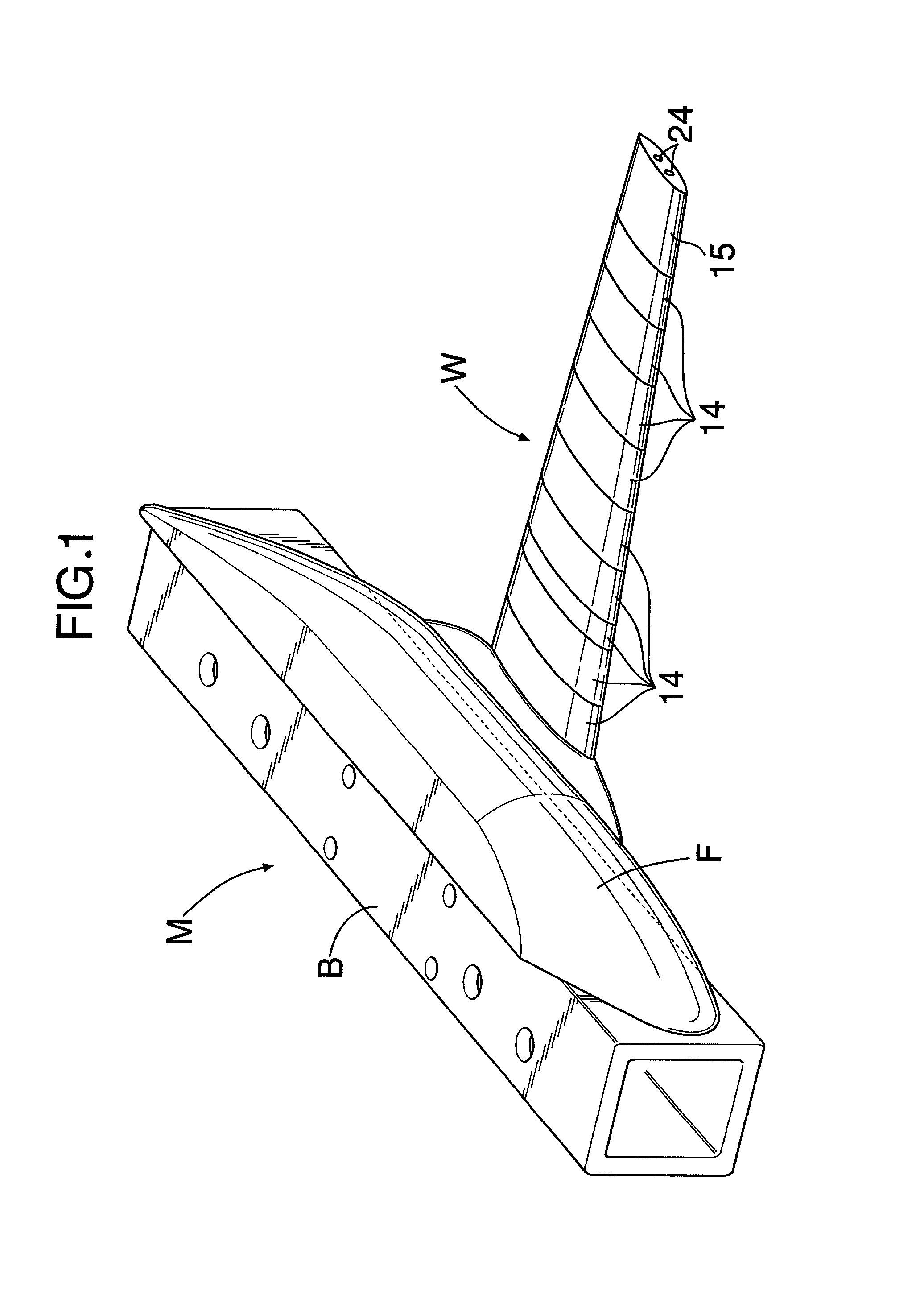
[0025]FIG. 1 shows a wind-tunnel test model M with which a flutter test for a main wing of an airplane is carried out. Since the shape of an airplane is symmetrical and the manner in which air flows around it is also symmetrical, the wind-tunnel test model M has only a left half of a fuselage F and a left test wing W, which are on the left side of a vertical plane passing through the axis of the airplane. Formed integrally on the right side face of the fuselage F is a support bracket B for supporting the wind-tunnel test model M in a wind tunnel.

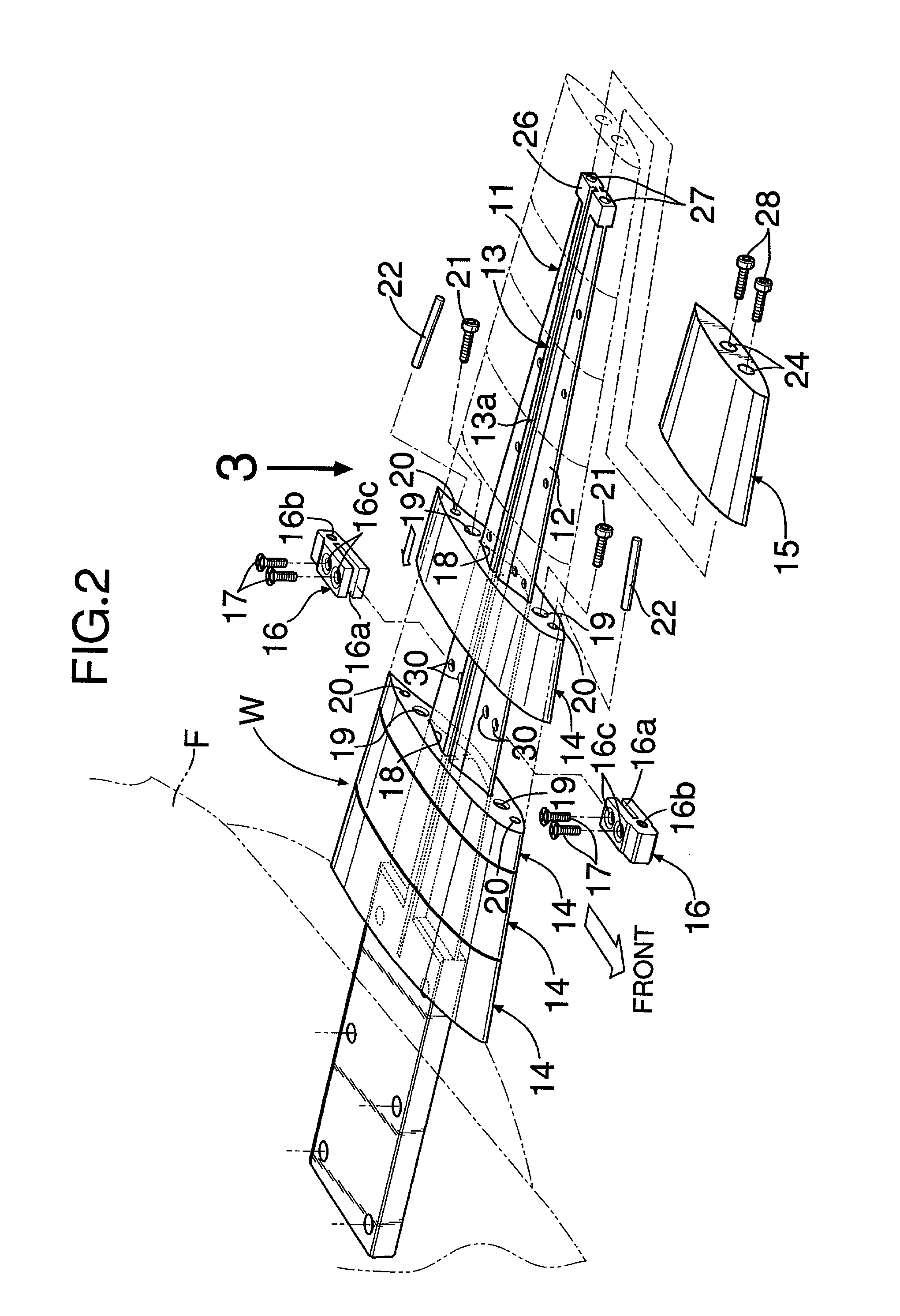
[0026]As is clear by referring to FIG. 2 together with FIG. 3, the test wing W has an elastic spar 11 made of metal, the elastic spar 11 forming a framework for the test wing W. The elastic spar 11 is formed from a plate 12 and a core 13, the plate 12 tapering down from the wing root toward the wing tip, and the core 13 having an H-shaped cross section and being formed integrally on a middle part, in the fore-and-aft direction, of the plate ...


PUM


Abstract

A flutter test model is provided that utilizes a novel approach for fixing wing elements to an elastic spar, resulting in reduced airflow disturbance. A test wing has an elastic spar that simulates the elasticity of a wing of an actual airplane, and a plurality of wing elements that simulate the external shape of the wing of the actual airplane. A pair of fore and aft anchor members are fixed to the elastic spar by bolts, the wing element that is formed by stereolithography is fitted around the anchor members from the wing tip side, and the wing element is fastened to the anchor members by bolts that run through the wing element from the wing tip side. A weight, which is a tungsten rod, is housed in a weight support hole formed in the wing element. The anchor members and the bolts are not exposed on the surface of the wing element and the airflow over the surface of the test wing is not disturbed when a flutter test is carried out in a wind tunnel, thereby enhancing the accuracy of the flutter test.

Description

BACKGROUND OF THE INVENTION[0001]1. Field of the Invention[0002]The present invention relates to a flutter test model that includes an elastic spar that simulates the elasticity of an actual wing, and a plurality of wing elements that simulate the external shape of the actual wing, the plurality of wing elements being fixed along the elastic spar to form a test wing.[0003]2. Description of Related Art[0004]A flutter test model for measuring the flutter characteristics of a main wing of an actual airplane by a wind-tunnel test is known, for example, in Japanese Patent Application Laid-open No. 7-27665.[0005]This flutter test model is formed by fixing a plurality of wing elements to an elastic spar made of metal, the wing elements being shaped using balsa wood and divided in the span direction, and the elastic spar simulating the flexural rigidity and the torsional rigidity of the main wings of the actual airplane. Bolts are used for fixing the wing elements to the elastic spar.[0006]...

Claims


Application Information

Patent Timeline
Patent Type & Authority Patents(United States)
IPC IPC(8): G06G7/48B64F5/00G01M9/08
CPCG01M9/08B64F5/0045B33Y80/00B64F5/60
Inventor OMOTANI, HIDEO
Owner AMERICAN HONDA MOTOR COMPANY
Why Eureka
Try Eureka