Energy recycling in clock distribution networks using on-chip inductors

a clock distribution network and energy recycling technology, applied in the direction of generating/distributing signals, instruments, computing, etc., can solve the problems of high power dissipation and heating, high power consumption in the clock distribution network, etc., and achieve the effect of reducing the output current of the clock driver through the clock n

Inactive Publication Date: 2006-07-25
AVAGO TECH WIRELESS IP SINGAPORE PTE
View PDF6 Cites 22 Cited by
  • Summary
  • Abstract
  • Description
  • Claims
  • Application Information

AI Technical Summary

Benefits of technology

[0005]In one aspect of the present invention, a clock distribution network for an integrated circuit includes a clock driver for generating a clock signal having a selected clock frequency, a clock net coupled to the clock driver wherein the clock net has a capacitive reactance, and an inductor coupled to the clock net wherein the inductor has an inductive reactance that is substantially equal and opposite to the capacitive reactance of the clock net at the selected clock frequency to minimize clock driver output current through the clock net.
[0006]In another aspect of the present invention, a method of distributing a clock signal in an integrated circuit includes the steps of generating a clock signal having a selected clock frequency from a clock driver, coupling the clock signal to a clock net having a capacitive reactance, and coupling an inductor to the clock net wherein the inductor has an inductive reactance that is substantially equal and opposite to the capacitive reactance of the clock net at the selected clock frequency to minimize clock driver output current through the clock net.

Problems solved by technology

High power consumption in clock distribution networks is a problem in large integrated circuit designs in which the clock power dissipation is dominated by dynamic or switching power, which is proportional to the wiring capacitance and the input capacitance of flip-flops connected to the clock net.
As a result, high power dissipation and heating may be generated by clock distribution networks.

Method used


Image

  • Energy recycling in clock distribution networks using on-chip inductors
  • Energy recycling in clock distribution networks using on-chip inductors
  • Energy recycling in clock distribution networks using on-chip inductors

Examples


Embodiment Construction

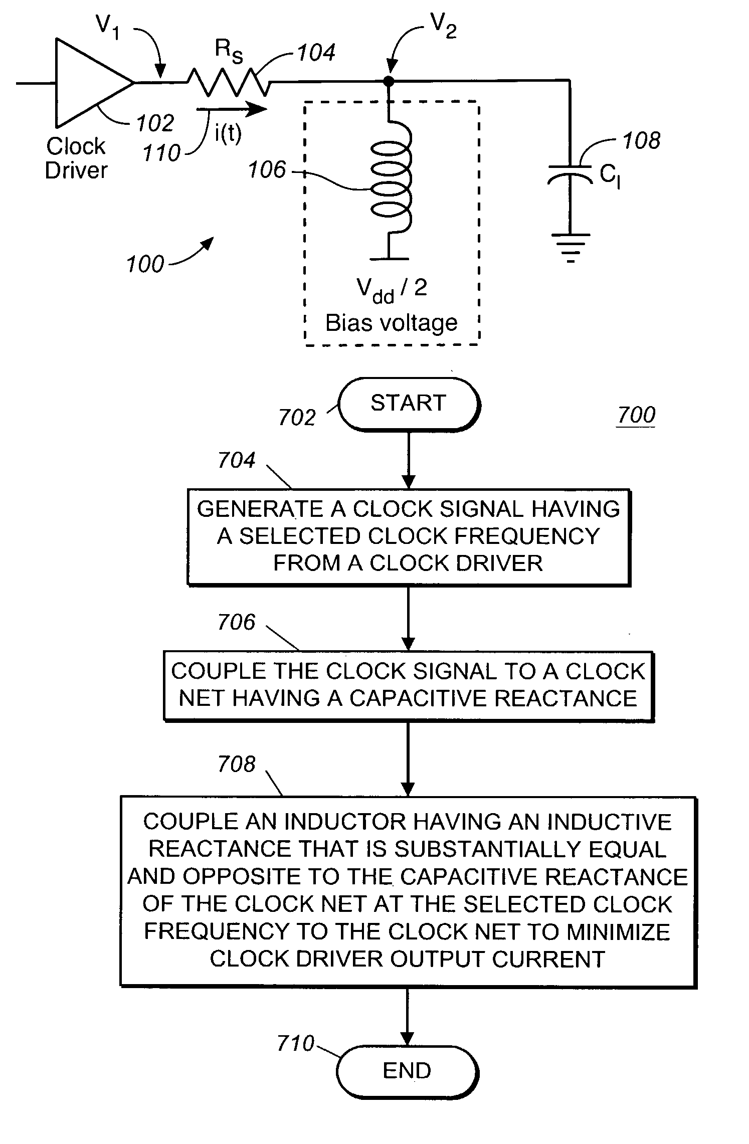
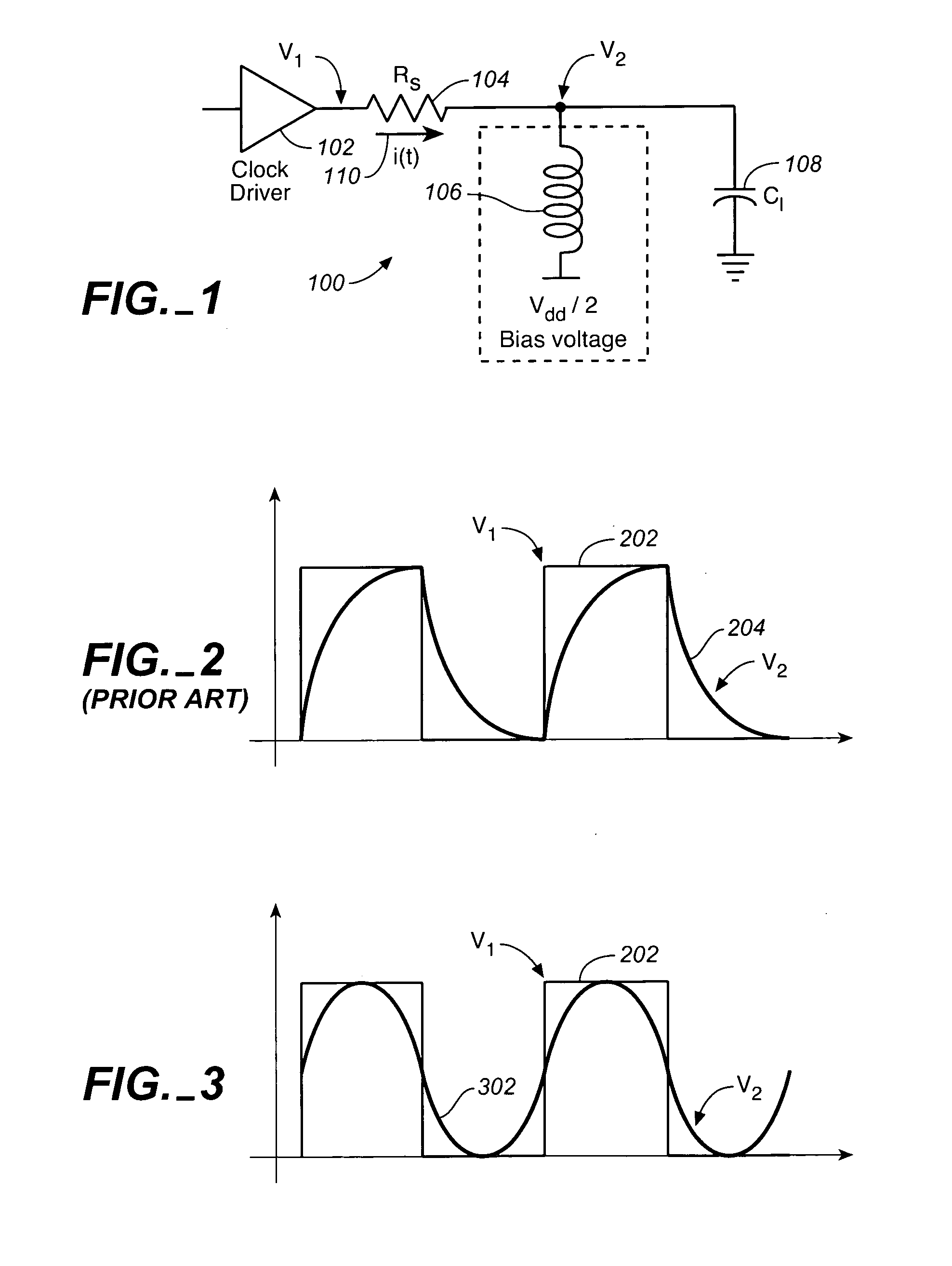
[0016]As technology accommodates more and more devices into integrated circuit designs, the increased number of clocked devices, generally called flip-flops, places greater demands on the system clock driver. Specifically, the input capacitance of the flip-flops connected to the system clock driver has a capacitive reactance that significantly increases the system clock current during switching of the clock signal between the power and ground rails. The capacitive reactance may be compensated by inductive reactance, however, in many clock distribution networks, the clock frequency is typically too low to make a short wire length resonant and too high for on-chip wires to make an efficient transmission line. These limitations prevent the use of previous resonant clock distribution networks at clock frequencies at about 500 Mhz and above used in currently available technology.

[0017]In one aspect of the present invention, a clock distribution network for an integrated circuit includes ...


PUM


Abstract

A clock distribution network for an integrated circuit includes a clock driver for generating a clock signal having a selected clock frequency, a clock net coupled to the clock driver wherein the clock net has a capacitive reactance, and an inductor coupled to the clock net wherein the inductor has an inductive reactance that is substantially equal to the capacitive reactance of the clock net at the selected clock frequency to minimize clock driver output current.

Description

BACKGROUND OF THE INVENTION[0001]1. Field of the Invention[0002]The present invention is directed to methods and devices for clock distribution networks in integrated circuits. More specifically, but without limitation thereto, the present invention is directed to a resonant clock distribution network for an integrated circuit.[0003]2. Description of the Prior Art[0004]High power consumption in clock distribution networks is a problem in large integrated circuit designs in which the clock power dissipation is dominated by dynamic or switching power, which is proportional to the wiring capacitance and the input capacitance of flip-flops connected to the clock net. As a result, high power dissipation and heating may be generated by clock distribution networks.SUMMARY OF THE INVENTION[0005]In one aspect of the present invention, a clock distribution network for an integrated circuit includes a clock driver for generating a clock signal having a selected clock frequency, a clock net cou...

Claims


Application Information

Patent Timeline
Patent Type & Authority Patents(United States)
IPC IPC(8): G06F17/50G06F1/10
CPCG06F1/10
Inventor ZARKESH-HA, PAYMANLOH, WILLIAM
Owner AVAGO TECH WIRELESS IP SINGAPORE PTE
Why Eureka
Try Eureka