Unitized thermoplastic foam structures

a thermoplastic foam and unitized technology, applied in the field of unitized thermoplastic foam structures, can solve the problems of not being able to stabilize the innerspring in the lateral or horizontal directions, not being able to bond or welded by polyurethane and other non-thermoplastic type foams, etc., to achieve the effect of limiting lateral deflection, superior support characteristics, and altering the support characteristics and feel of the innerspring

Inactive Publication Date: 2006-08-01
SEALY TECH LLC
View PDF45 Cites 50 Cited by
  • Summary
  • Abstract
  • Description
  • Claims
  • Application Information

AI Technical Summary

Benefits of technology

[0007]In one general aspect of the invention, there is provided a unitized thermoplastic foam structure made of two or more thermoplastic foam components which are thermally bonded, welded or fused together to form a three-dimensional foam structure which is combined with an innerspring assembly. In one form, the three-dimensional foam structure serves as both a support base or deck for the innerspring assembly, and as a perimeter wall or at least partial encapsulation of the innerspring assembly. In a mattress embodiment, one of the foam components is in the form of a foam deck which has parallel planar sides, with one of the sides serving as a support surface for an innerspring. With an innerspring positioned on one of the sides of the foam deck, at lest one additional foam component, such as a wall or other vertical structure, which is thermally bonded or fused to the foam deck, is oriented to rise from the plane of the deck in a third dimension form a unitized foam structure about or in connection with the innerspring. The foam deck is in one embodiment a repeated beam structure with multiple parallel box beams forming a semi-rigid deck which supports one side of an innerspring assembly. In another embodiment the foam deck has a solid foam cross-section. The combination of the unitized foam structure and an innerspring assembly can be used to provide a one-sided mattress with superior support characteristics resulting from the flexibility of the foam deck. The vertical profile of the box beams of the foam deck defines a degree of stiffness and flexure which responds to localized loads on the overlying innerspring. The stiffness or density of the foam deck alters the support characteristics and feel of the innerspring, whereby a mattress can be designed accordingly for a desired feel. In a preferred embodiment, the foam deck is formed by a plurality of extruded foam beams which are bonded or fused together by welds along abutting edges.
[0008]In accordance with another aspect of the invention, a mattress is formed by the combination of an innerspring and a foam deck adjacent the innerspring, and extruded foam rails located at edges of the innerspring and in contact with the foam deck, the foam rails being thermally bonded to the foam deck to form a unitized foam structure about the innerspring. The unitized foam structure functions with the innerspring to encapsulate and support the innerspring, to limit lateral deflection, to dampen individual coils of the innerspring, and to provide complimentary flexible support. The novel method of manufacture by which the unitized foam structure is integrated with the innerspring involves the thermal bonding, welding or fusing of thermoplastic foam components about the innerspring, eliminating the requirement of mechanical attachment of foam pieces to the innerspring.

Problems solved by technology

Also, polyurethane and other non-thermoplastic type foams cannot be bonded or welded by any heat-source process due to their decomposition properties.
It also only provides support in the vertical direction and does nothing to stabilize the innerspring in the lateral or horizontal directions.

Method used


Image

  • Unitized thermoplastic foam structures
  • Unitized thermoplastic foam structures
  • Unitized thermoplastic foam structures

Examples


Embodiment Construction

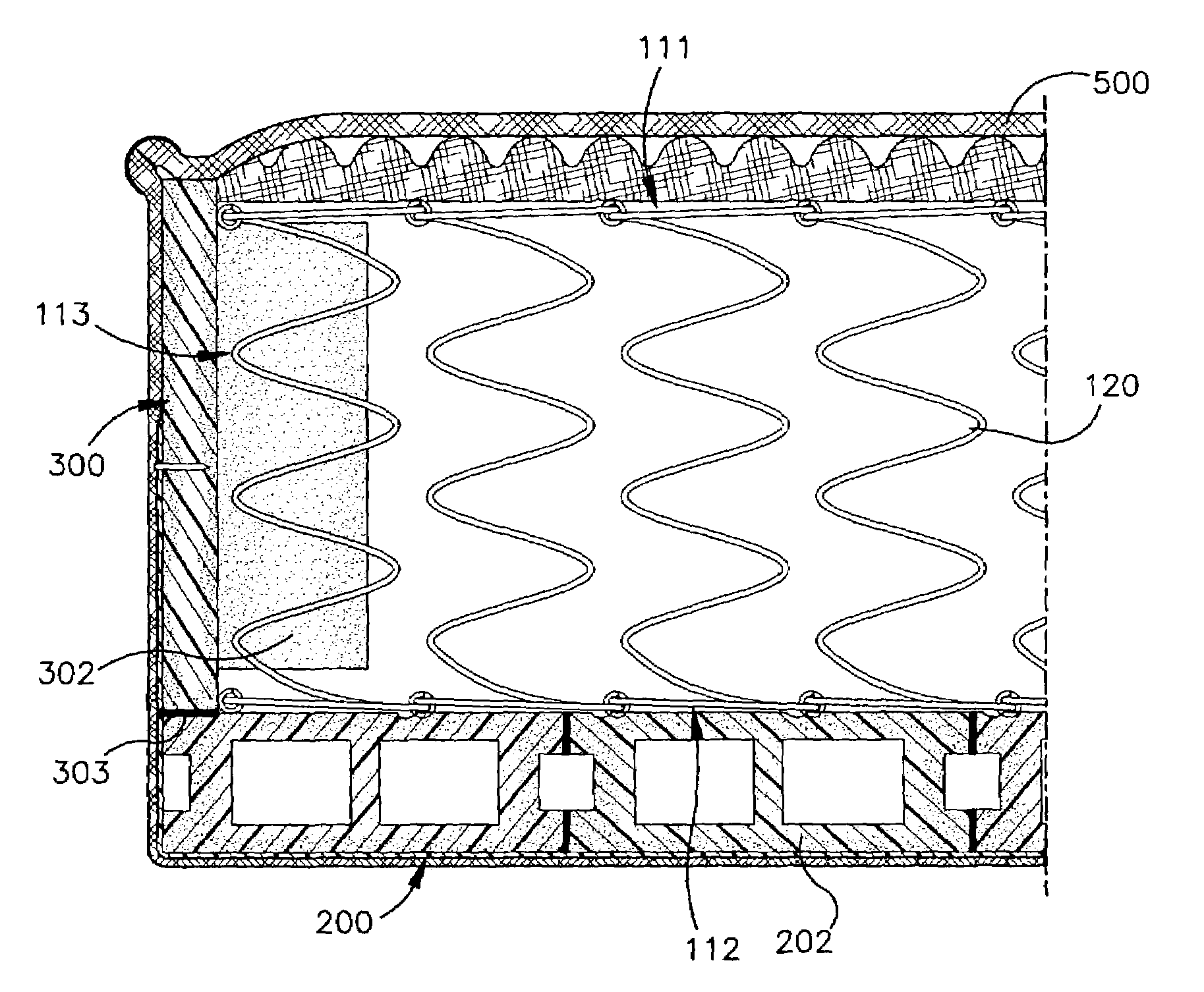
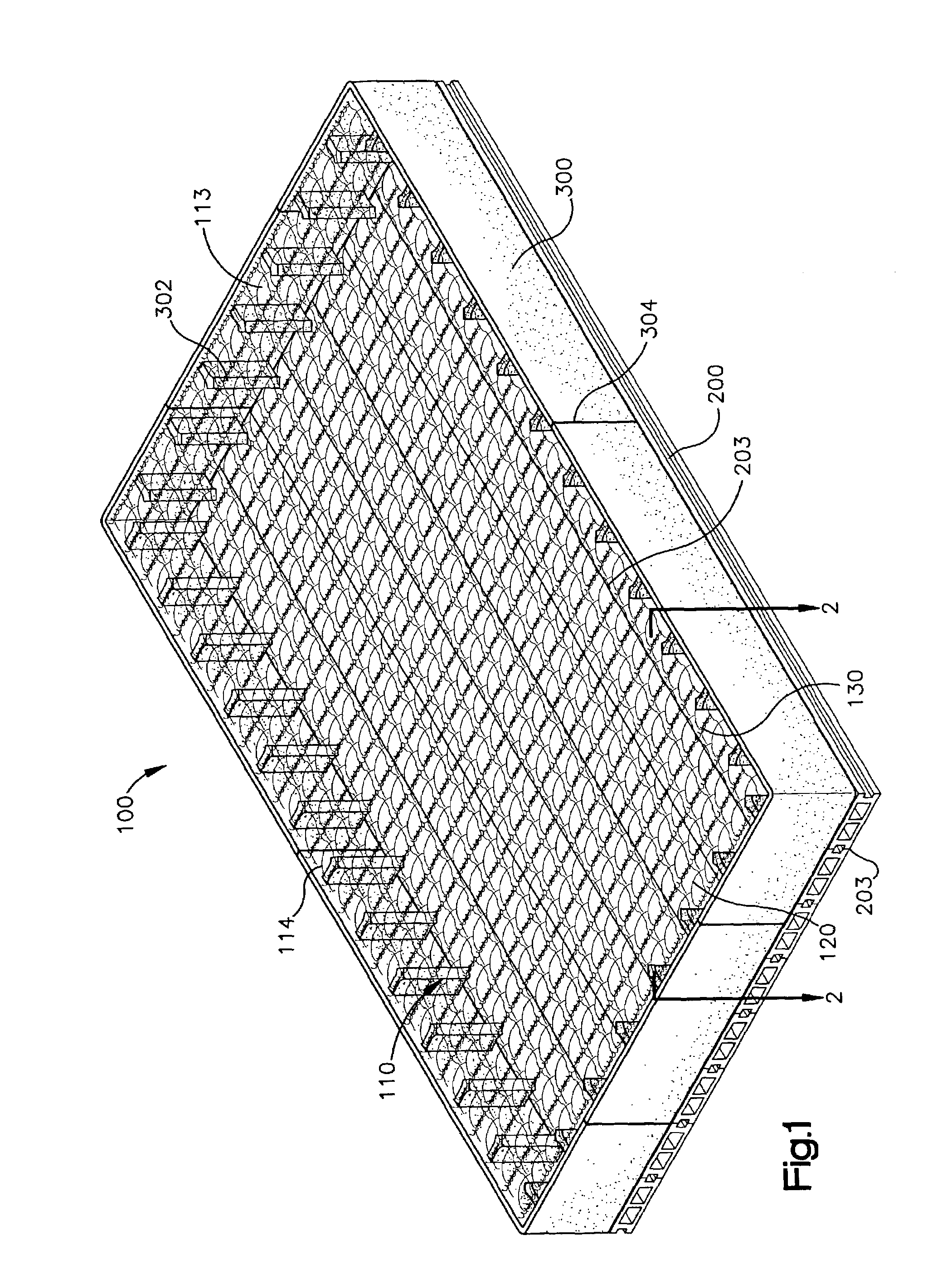
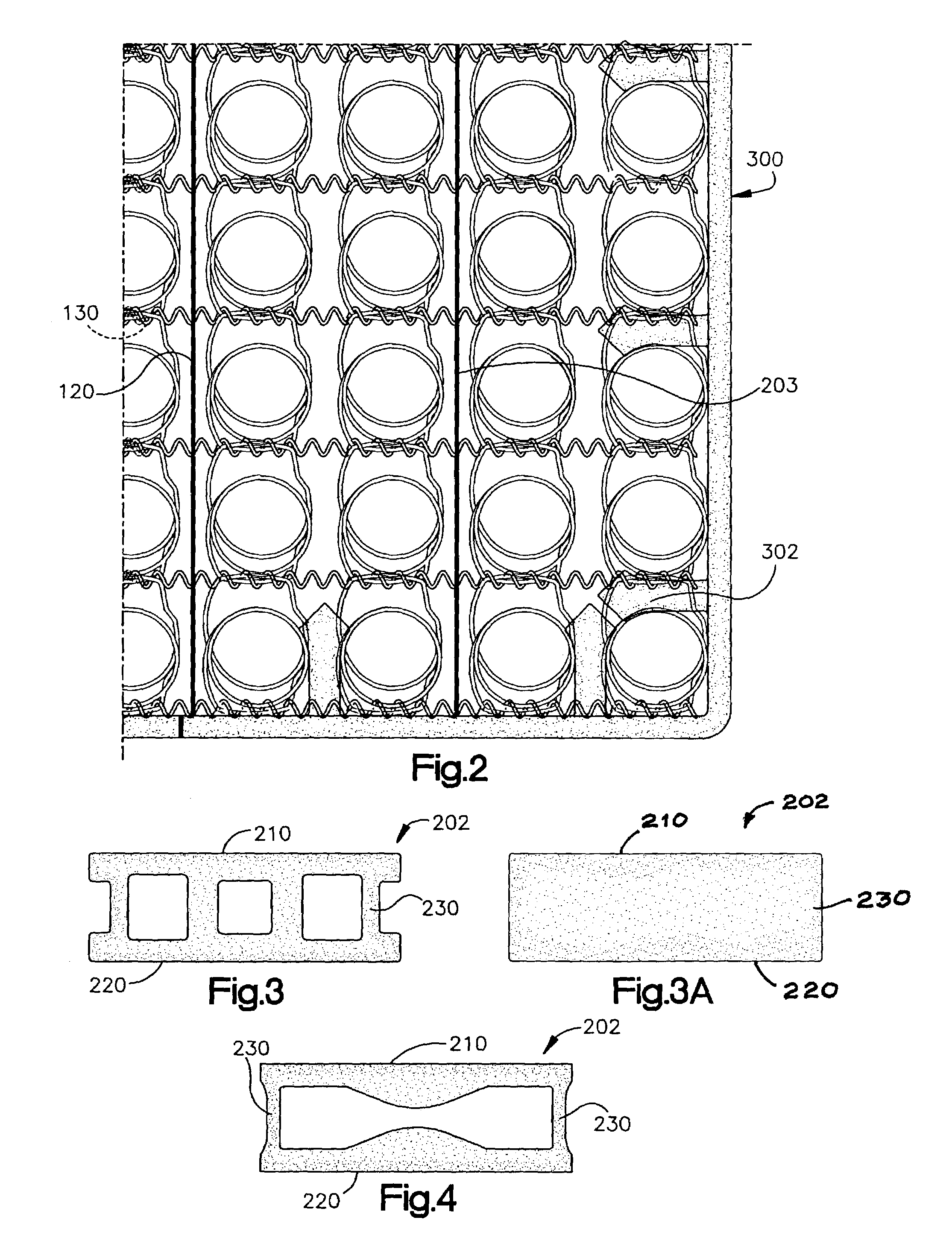
[0027]With reference to FIG. 1, there is illustrated a unitized foam structure mattress, referenced generally as 100, which in this particular embodiment of the invention is in the form of a one-sided mattress, with a unitized foam structure providing a structural encapsulation and base for an innerspring, as further described. The unitized foam structure mattress includes an innerspring 110 (also referred to herein as an “innerspring assembly”) which is made up of a plurality of wire form coils 120 which are interconnected or laced together by helical wires 130 as known in the art, in an array to form an assembly which has a first support side generally defined by aligned first ends of the coils or spring elements, and a second support side generally defined by the aligned second ends of the coils or spring elements, the first and second support sides being parallel, and a perimeter about the first and second support sides defined by perimetrical coils at the edges of the array, de...


PUM

PropertyMeasurementUnit
structure mattressaaaaaaaaaa
perimeteraaaaaaaaaa
thickness dimensionaaaaaaaaaa

Abstract

Three-dimensional unitized thermoplastic foam structures are made by thermoplastic welding of different foam components. The unitized foam structures may include a planar base to which other foam components are welded to project from the base and provide a flexible three-dimensional structure. The thermal bonding or welding of the thermoplastic foam components creates a unitized structure which is both flexible and load bearing. For mattress and seating applications, the welded foam structures may be combined with an innerspring, and certain of the foam components of the structure may mechanically engage parts of the innerspring. The preferred foam deck has first and second panels interconnected by one or more webs. One or more foam decks may be employed. Other foam components may be attached to the foam decks or other components. The utilized foam structures can be employed as single or double-sided mattresses, seating structures or other flexible support structures.

Description

FIELD OF THE INVENTION[0001]The present invention pertains generally to structures made of foam material, and to foam parts, which are assembled or bonded together, to form three-dimensional utilized structures.BACKGROUND OF THE INVENTION[0002]Different types of foam and foam parts have been used extensively in seating and bedding as flexible support material. Semi-rigid open and closed cell foams of polyethylene, polyurethane or polystyrene have been used in combination with other components and load-bearing structures, such as wire form innersprings and framing to form flexible supports, such as described in U.S. Pat. Nos. 5,048,167; 5,469,590; 5,467,488 and 5,537,699 and 5,787,532. In most of these springs support products, the foam pieces surround or interfit with spring elements, and rely on mechanical connection with the spring elements to keep the foam pieces in place. Foam pieces have also been adhesively bonded and combined with innersprings. The types of foams used in thes...

Claims


Application Information

Patent Timeline
Patent Type & Authority Patents(United States)
IPC IPC(8): A47C23/04A47C27/05A47C27/14
CPCA47C27/053B29C65/4815B29C66/727A47C27/056B29C65/20B29C65/52B29C66/1142B29C66/43B29K2101/12B29K2105/04B29L2031/751B29C65/00B29C66/433B29C66/438B29C66/474A47C23/04A47C27/05
Inventor BARMAN, BRUCE G.DEMOSS, LARRY
Owner SEALY TECH LLC
Why Eureka
Try Eureka