

Tire monitoring device with coupled power source
- Summary
- Abstract
- Description
- Claims
- Application Information
AI Technical Summary
Benefits of technology
Problems solved by technology
Method used
Image

Examples
first embodiment
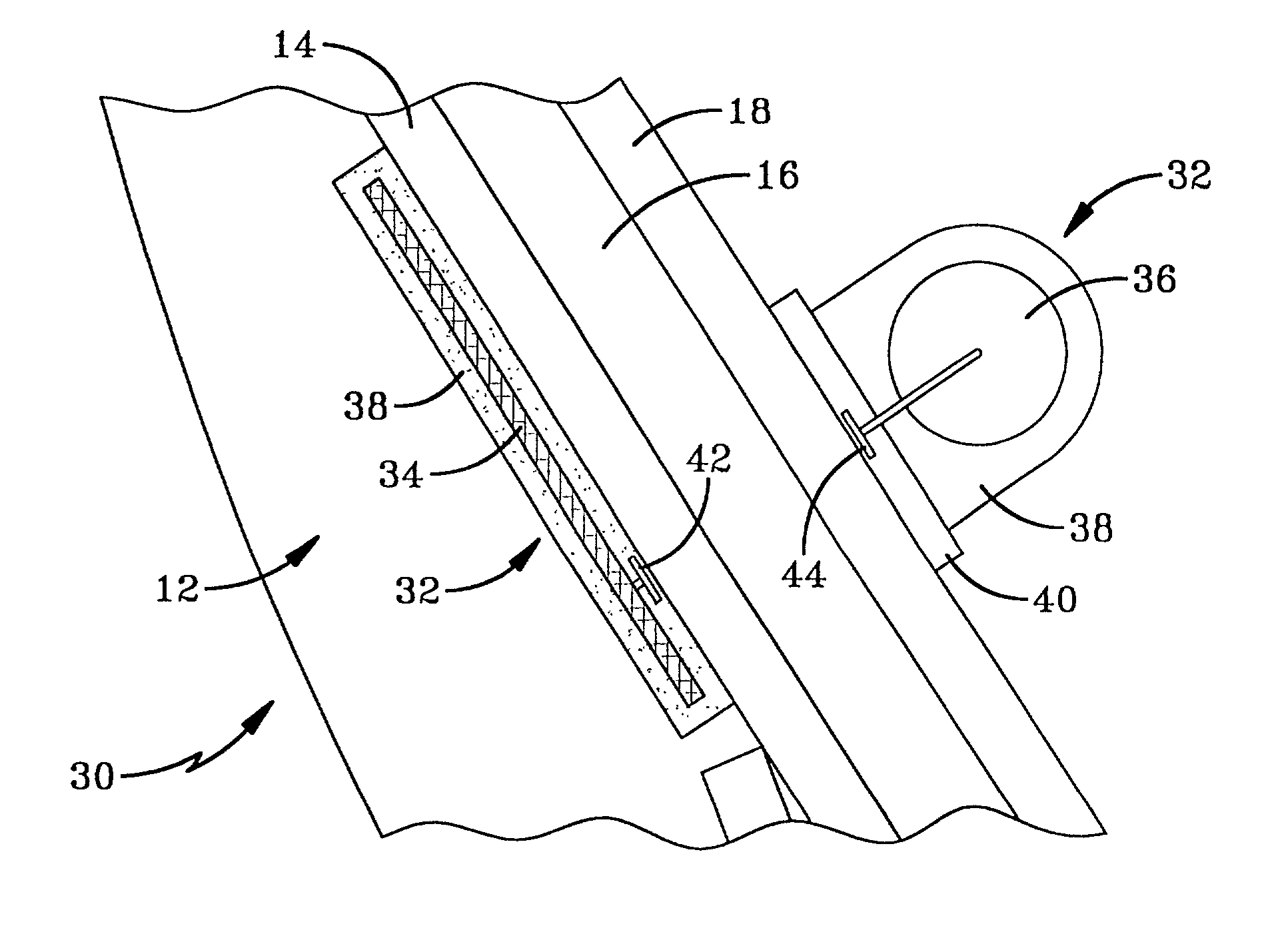
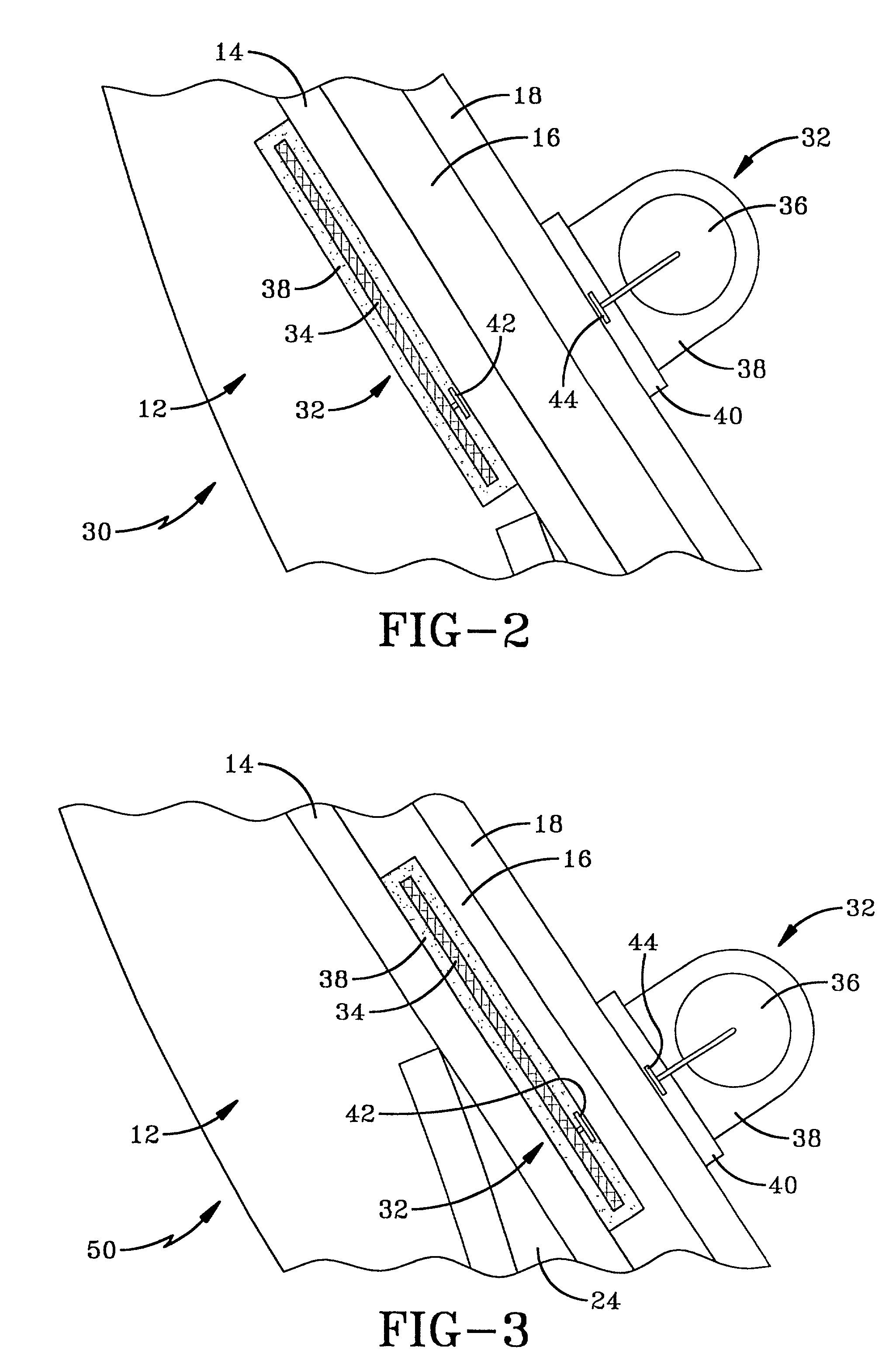
[0024]the invention is depicted in FIG. 2 with the pneumatic tire indicated generally by the numeral 30. Tire 30 includes many of the same body elements as tire 10 but further includes an electronic monitoring device 32 mounted to pneumatic tire 30. Electronic monitoring device 32 includes a monitoring package 34 mounted within body 12 and a power source 36 mounted to innerliner 18. Monitoring package 34 receives power from power source 36 through electrical coupling. Specifically, monitoring package 34 receives power through close proximity electromagnetic coupling.
[0025]Electronic monitoring package 34 may include a variety of components that are known in the art to monitor at least one engineering condition of pneumatic tire 30 and transmit information out of tire 30. Electronic monitoring package 34 may include at least one sensing element that monitors or measures an engineering condition of tire 30. Monitoring package 34 may further include a device to store the information or...
embodiment 60
[0032]Tire embodiment 60 is depicted in FIG. 4 with monitoring package 34 positioned between body ply 16 and innerliner 18. Tire 70 of FIG. 5 shows monitoring package 34 embedded within innerliner 18. Tire 80 of FIG. 6 depicts an embodiment where monitoring package 34 is mounted to the inner surface of innerliner 18. In each of the embodiments of FIGS. 4, 5, and 6, first and second coupling elements 42 and 44 are aligned and spaced apart to provide power between power source 36 and monitoring package 34.
[0033]Tire 90 is depicted in FIG. 7 with monitoring package 34 embedded within a patch 92 connected to innerliner 18. Patch 92 may be a rubber patch that is fabricated separately from body 12 of tire 90 and later connected to innerliner 18. In another embodiment, patch 92 is an anchoring patch that is connected to innerliner 18 before body 12 of tire 90 is cured. The green tire curing process cures body 12 and anchoring patch 92 along with monitoring device 34 embedded within anchori...
PUM
 Abstract
Description
Claims
Application Information