
Steel-super high toughness concrete lightweight combined beam pier top bridge surface continuous structure and construction method thereof

An ultra-high toughness, concrete technology, applied in the direction of bridges, bridge parts, bridge materials, etc., can solve the problems of falling beams, inconvenient maintenance, damage to the continuous structure of the bridge deck, etc. , the effect of protecting integrity

Pending Publication Date: 2018-02-02
CHINA HIGHWAY ENG CONSULTING GRP CO LTD +1
View PDF0 Cites 2 Cited by
  • Summary
  • Abstract
  • Description
  • Claims
  • Application Information

AI Technical Summary

Problems solved by technology

At the same time, simply supported girder bridges are weak in seismic resistance. Under the action of external forces beyond the design range, the longitudinal deformation of the bridge is too large, which is easy to cause damage to the continuous structure of the bridge deck. even fall off the stand
After the existing bridge deck continuous structure is damaged, maintenance is inconvenient and costly

Method used


Image

  • Steel-super high toughness concrete lightweight combined beam pier top bridge surface continuous structure and construction method thereof
  • Steel-super high toughness concrete lightweight combined beam pier top bridge surface continuous structure and construction method thereof
  • Steel-super high toughness concrete lightweight combined beam pier top bridge surface continuous structure and construction method thereof

Examples


Embodiment Construction

[0027] In order to facilitate the understanding of the present invention, the present invention will be described more fully and in detail below in conjunction with the accompanying drawings and preferred embodiments, but the protection scope of the present invention is not limited to the following specific embodiments.

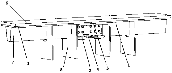
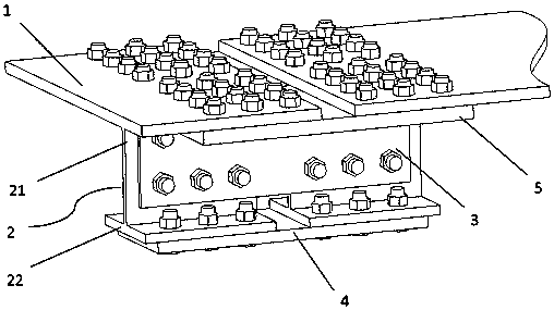
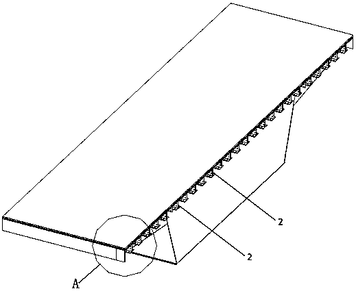
[0028] Such as Figure 1-Figure 4 As shown, a steel-ultrahigh toughness concrete light-duty composite girder pier top continuous structure of the present invention includes a bridge pier and two steel box girders on the top of the bridge pier, and the continuous structure is arranged on the adjacent steel box girder deck 1, the adjacent bridge decks 1 are combined to form a continuous whole, which includes inverted T ribs 2, inverted T rib web connecting plates 3, inverted T rib bottom connecting plates 4, roof connecting plates 5, two A plurality of inverted T-ribs 2 are arranged laterally at intervals on the bottom surface of the joint of the bridge deck. ...


PUM


Abstract

The invention discloses a steel-super high toughness concrete lightweight combined beam pier top bridge surface continuous structure. The steel-super high toughness concrete lightweight combined beampier top bridge surface continuous structure is arranged between adjacent steel box beam bridge surface plates, combines the adjacent bridge surface plates together to form a continuous whole, and comprises inverted-T ribs, inverted-T rib web connecting plates, inverted-T rib bottom plate connecting plates and top plate connecting plates. The multiple inverted-T ribs are transversely arranged on the bottom surface of the joint of the two bridge surface plates at intervals, and the inverted-T ribs on the two bridge surface plates are in one-to-one correspondence. Webs of the two corresponding inverted-T ribs are connected through the corresponding inverted-T rib web connecting plate; bottom plates of the two corresponding inverted-T ribs are connected through the corresponding inverted-T rib bottom plate connecting plate; and between the adjacent inverted-T ribs, the two bridge surface plates are connected through the top plate connecting plates. According to the continuous structure, adjacent box beams are connected as a whole through the inverted-T ribs and the connecting plates, under the effect of an earthquake, the damage mode of the continuous structure is that bolts are sheared off, in restoration after the earthquake, only the sheared-off high-strength bolts need to be replaced, and STC is partially repaired, so that repair is easy and convenient.

Description

technical field [0001] The invention relates to a bridge deck continuous structure and a construction method thereof. Background technique [0002] Simply supported girder bridge is a girder bridge whose main load-bearing structure is a girder whose two ends are respectively supported on a movable support and a hinged support. It is the earliest and most widely used bridge shape among girder bridges. Fixed structure, under normal circumstances, one end of simply supported beam can be freely deformed, so no redundant internal force will be generated, its structure is simple, easy to erect, and the internal force of the structure is not affected by foundation deformation and temperature change. However, there are many expansion joints on the bridge deck of simply supported beam bridges, which makes driving uncomfortable. In order to effectively reduce the number of deck expansion joints of simply supported girder bridges, continuous bridge deck structures are widely used. At...

Claims


Application Information

Patent Timeline
IPC IPC(8): E01D19/12E01D2/04E01D101/30E01D101/26
CPCE01D2/04E01D19/125E01D2101/26E01D2101/30
Inventor 吴敬武邵旭东刘闯孙平宽刘新华吕晓宇王成斌张法潘德雄
Owner CHINA HIGHWAY ENG CONSULTING GRP CO LTD
Learn More