Closing device for a container

a container and closing device technology, applied in the field of container closing devices, can solve the problem of using known devices

Inactive Publication Date: 2006-08-01
ARACARIA
View PDF12 Cites 73 Cited by
  • Summary
  • Abstract
  • Description
  • Claims
  • Application Information

AI Technical Summary

Benefits of technology

[0039]It is particularly preferable for the closing device, excluding the handle, to be made, in particular completely, of metal, for example of stainless steel. This giv

Problems solved by technology

In addition, a further serious disadvantage is that the known devices can be used only on special

Method used


Image

  • Closing device for a container
  • Closing device for a container
  • Closing device for a container

Examples


Embodiment Construction

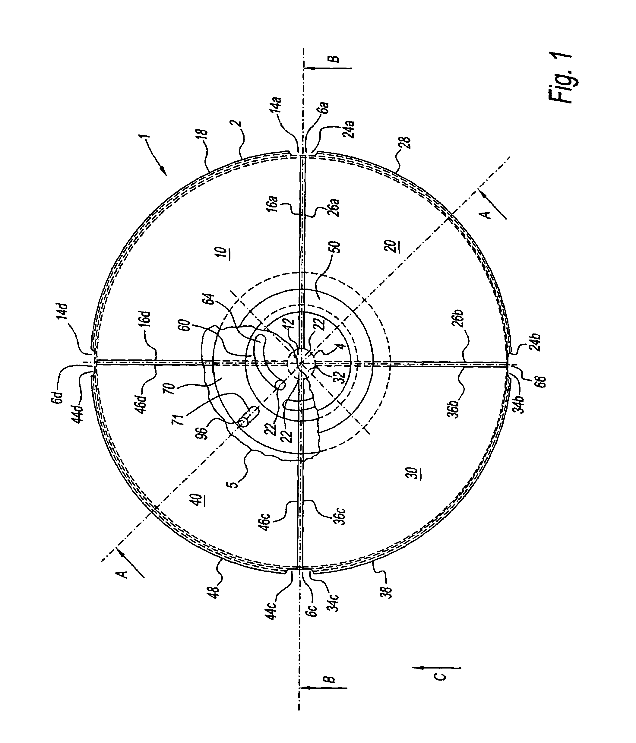
[0054]FIG. 1 shows an embodiment of the closing device 1 according to the invention with a closing element arrangement 2, comprising four closing elements 10, 20, 30, 40 which are substantially in the shape of segments of a circle, and a rotationally symmetrical and rotatable handle 50 which is arranged centrally with respect to the closing device 1. Each of the four closing elements 10, 20, 30, 40 has in each case a central arc-shaped cutout 12, 22, 32, 42 and in each case two mutually adjoining cutouts 14d, 14a, 24a, 24b, 34b, 34c, 44c, 44d which are arranged at the outer corners of the closing elements located on the circumference.

[0055]In the closure position of the closing device 1 shown in FIG. 1, the cutouts 12, 22, 32, 42 substantially form a central circular cutout 4 of the closing element arrangement 2. The cutouts 14d, 14a, 24a, 24b, 34b, 34c, 44c, 44d form four cutouts 6a, 6b, 6c, 6d arranged at 90° along the circumference of the closing element arrangement 2.

[0056]The f...


PUM


Abstract

The invention relates to a closing device for a container with an opening, in particular for a cooking pot with an outwardly protruding pouring edge, said closing device comprising a lid for closing the opening of the container, a closing element arrangement with at least a first closing element, and a movement device for moving the first closing element, said first closing element being able to be moved in an inward direction upon actuation of the movement device and moving upward at least in parts during the inwardly directed movement.

Description

BACKGROUND OF THE INVENTION[0001]1. Field of the Invention[0002]The invention relates to a closing device for a container in general and for a cooking pot or steam pressure cooking pot in particular.[0003]2. Description of Related Art[0004]At a time of increasing health awareness, there is also a greater demand for food preparation methods which are advantageous from the point of view of nutrition. At the same time, in a hectic world in which people want to and are able to spend less and less time on everyday household chores, there is a desire for fast and efficient food preparation. Steam pressure cooking pots satisfy these two apparently conflicting requirements outstandingly by permitting rapid and gentle cooking of food.[0005]In principle, steam pressure cooking pots have been known for decades. However, the known steam pressure cooking pots have a number of disadvantages.[0006]From the fifties, for example, and more specifically from patent specification DE 896 409, a steam pr...

Claims


Application Information

Patent Timeline
IPC IPC(8): A47J27/00A47J27/08A47J27/09B65D45/00B65D45/34
CPCA47J27/0813Y10S220/912A47J27/08
Inventor SCHULTZ, HORST
Owner ARACARIA
Why Eureka
Try Eureka