

Elevator group control method using destination floor call input
a technology of destination floor and call input, which is applied in the direction of elevators, transportation and packaging, etc., can solve the problems of inconvenience for waiting passengers, too expensive in large buildings, and congestion, so as to improve passenger service, reduce passenger waiting time, and reduce the effect of waiting tim
- Summary
- Abstract
- Description
- Claims
- Application Information
AI Technical Summary
Benefits of technology
Problems solved by technology
Method used
Image

Examples
Embodiment Construction
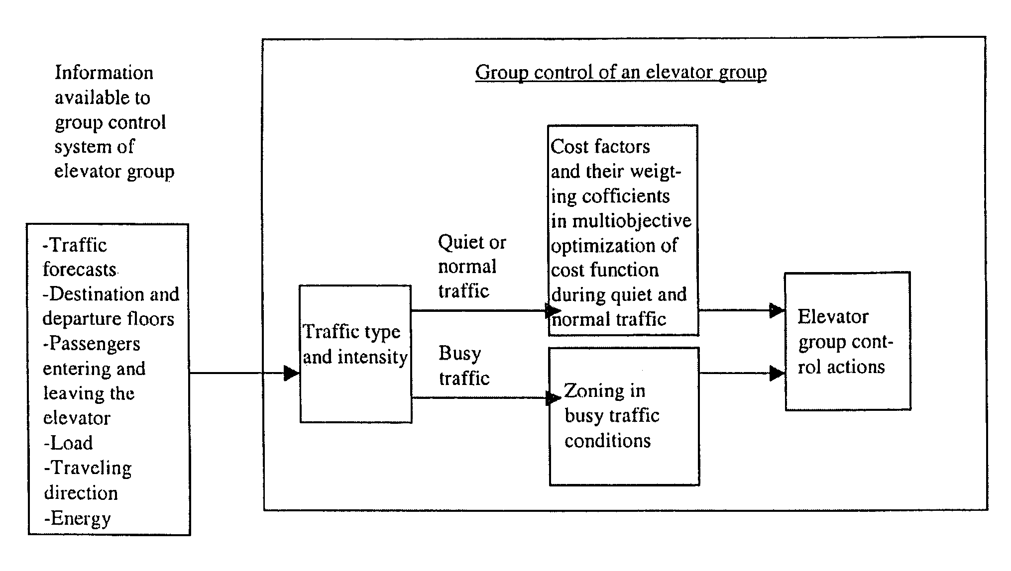
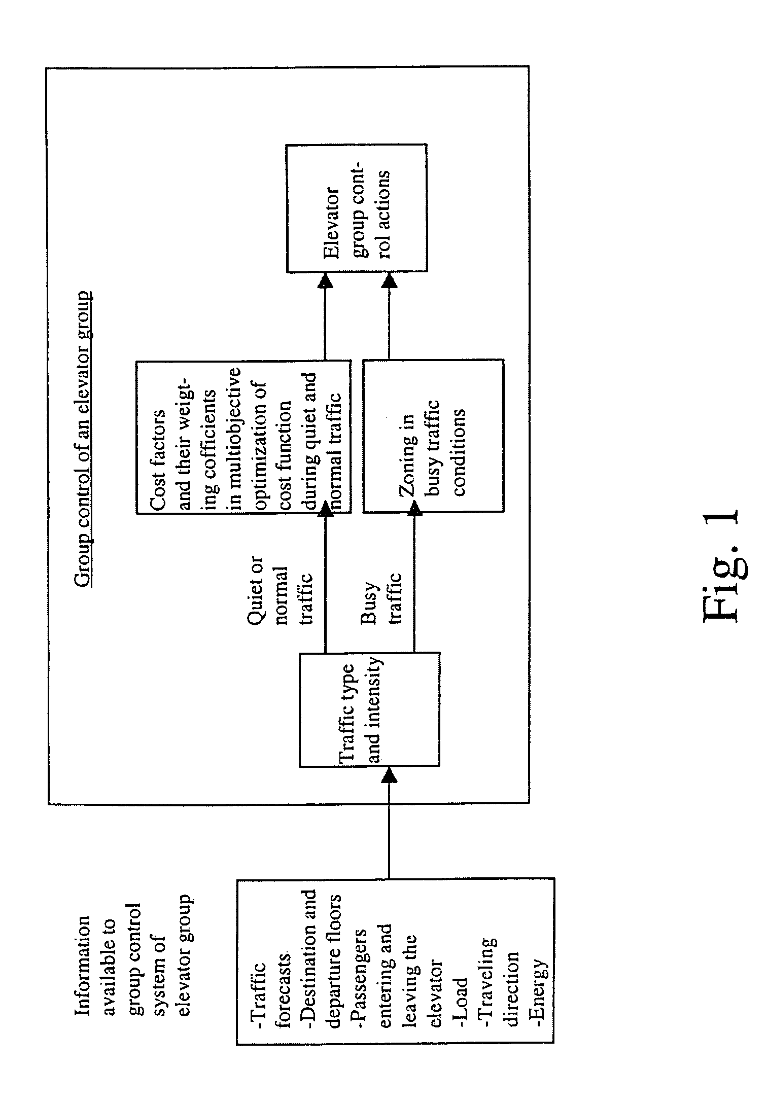
[0027]The diagram in FIG. 1 visualizes the method of the invention, wherein the input of calls to the elevators in the elevator group is implemented using destination floor call input and the traffic within the elevator group is optimized using as a control method either multiobjective optimization or dynamic zoning, depending on the intensity and type of the traffic. The elevator group is controlled by a computer configured for this purpose.
[0028]Information for use by the group control system of the elevator group is obtained from traffic forecasts regarding the current traffic type and intensity. In forecast statistics, information is collected e.g. from car load weighing devices and / or light cells and / or destination floor call buttons, which can be utilized expressly in connection with destination control. From destination call buttons, preferably information representing traffic arrival times and passengers' floors of arrival and departure is obtained. Thus, the elevator group ...
PUM
 Abstract
Description
Claims
Application Information