Projector

a projector and optical element technology, applied in the field of projectors, can solve the problems of difficult to ensure the stable operation the cost of the phase modulation optical element or the driving circuit itself, and the inability to avoid a certain degree or more of transmittance reduction

Inactive Publication Date: 2006-08-01
SEIKO EPSON CORP
View PDF19 Cites 3 Cited by
  • Summary
  • Abstract
  • Description
  • Claims
  • Application Information

AI Technical Summary

Benefits of technology

[0008]Aspects of the invention can provide a projector capable of forming a projected image with an apparently seamless smooth image quality in the stable state. Further, the invention can provide a projector capable of forming a projected image with less luminance reduction and nonuniform luminance.

Problems solved by technology

Therefore, it is not easy to ensure the stable operation of the phase modulation optical element.
As a result, the phase modulation optical element or the driving circuit itself can become costly, or the resulting image tends to be instable.
Further, with the foregoing related art projector, the transmittance reduction to a certain degree or more cannot be avoided, nor the occurrence of the nonuniform transmittance cannot be avoided, either.
Accordingly, the reduction of luminance and the nonuniform luminance of the projected image inevitably occur.

Method used


Image

  • Projector
  • Projector
  • Projector

Examples


Embodiment Construction

[0032]Below, the configuration of a projector in accordance with a first exemplary embodiment of the invention will be described by reference to the accompanying drawings.

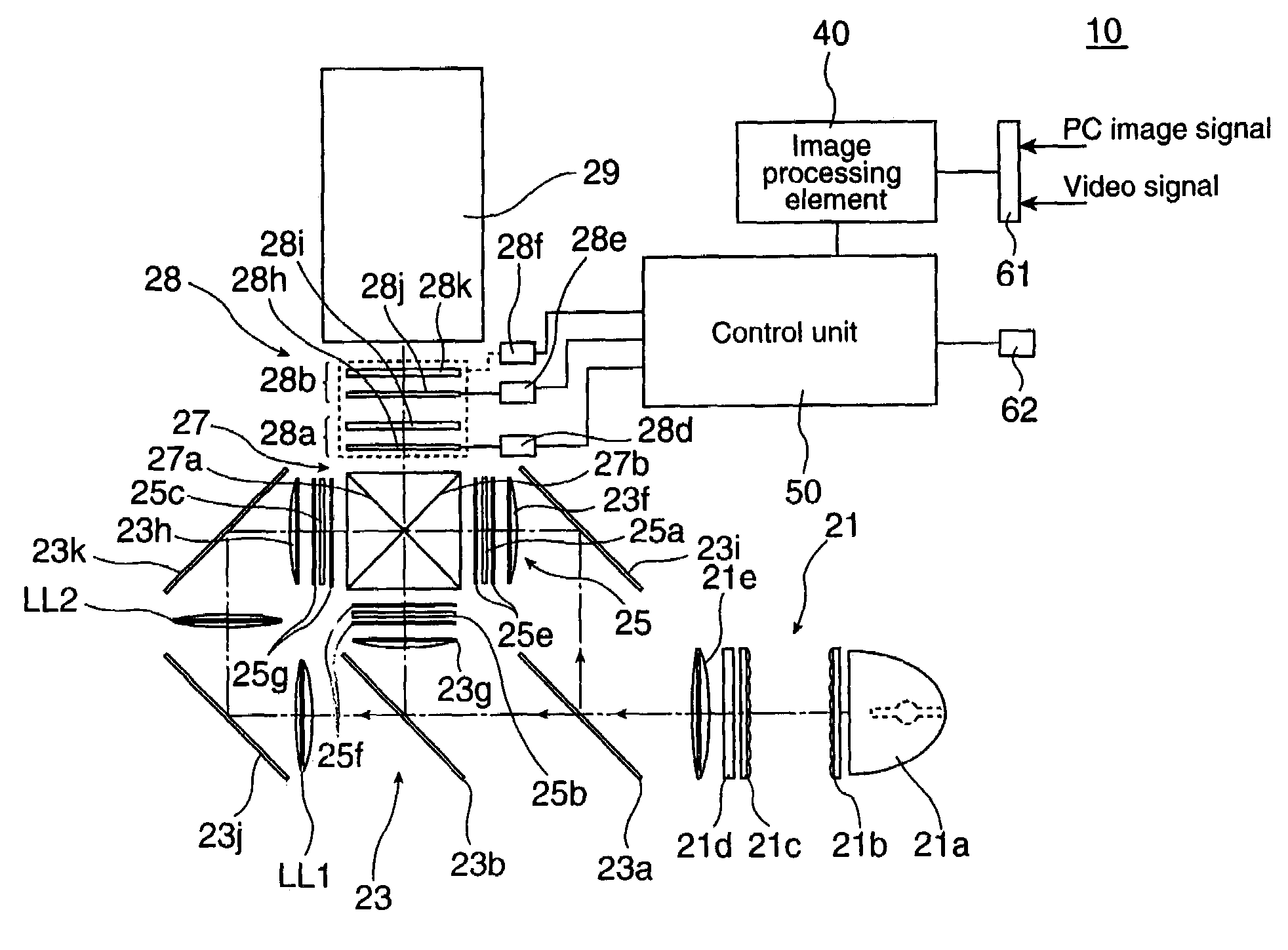
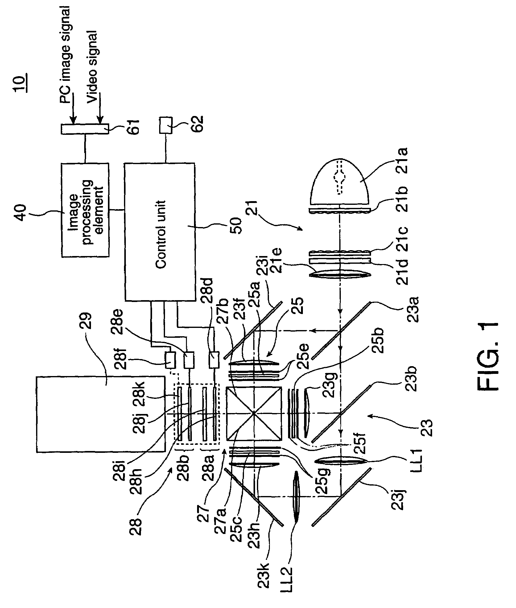
[0033]FIG. 1 is a diagram for illustrating the optical system of the projector of the first exemplary embodiment. The projector 10 has a light source unit 21 for generating a source light, a light splitting optical system 23 for splitting the source light from the light source unit 21 into three colors of R, G, and B, a light modulating element 25 to be illuminated by illumination lights of respective colors emitted from the light splitting optical system 23, a light synthesizing optical system 27 for synthesizing image lights of respective colors from the light modulating element 25, a BM removing unit 28 for performing a kind of an optical low-pass filtering processing on the image light synthesized by the light synthesizing optical system 27, and a projection lens 29, which is a projection optical system, for pr...


PUM


Abstract

Aspects of the invention can provide a projector capable of forming a projected image with an apparently seamless and smooth image quality in the stable state. As for the image light passed through a first unit, the polarization direction thereof can be appropriately rotated by a λ / 2 phase plate, and a part of the image light can be split in the Y direction by a birefringent plate. When this is projected as it is, an image composed of a plurality of two dimensionally arranged pixels, pixels corresponding to the split image, and a black matrix area can be formed on a screen. As for the image light passed through a second unit, the polarization direction thereof can be appropriately rotated by a λ / 2 phase plate, and a part of the image light can be split in the Y direction by a birefringent plate. Then, an image composed of the pixels in the previous stages, the pixels corresponding to the split images, and the black matrix area can be formed on the screen.

Description

BACKGROUND OF THE INVENTION[0001]1. Field of Invention[0002]Aspects of the invention can relate to a projector for projecting an image using a liquid crystal display panel, and other display units.[0003]2. Description of Related Art[0004]In related art projectors having a display element composed of discrete pixels, there are some projectors which incorporate an optical unit configured such that a plurality of wobbling elements each having a switch type phase modulation optical element which are optically transparent, and composed of a ferroelectric liquid crystal, and the like, and an optically transparent birefringent medium are stacked one on another. See, for example, JP-A-7-36054.[0005]With such a projector, the operation of the phase modulation optical element can be switched during one frame, thereby to alternately switch the polarization direction of the light passing through the birefringent optical element to the orthogonal direction. As a result, the optical path of the l...

Claims


Application Information

Patent Timeline
Patent Type & Authority Patents(United States)
IPC IPC(8): G03B21/14G02B27/00G02B27/14G02B27/28H04N9/31
CPCG02B27/1046G02B27/145G02B27/149H04N9/3197G02B27/286H04N9/3105G02B27/283G03B21/14G03B21/00G02B27/28
Inventor UEHARA, KATSUYUKINISHIDA, KAZUHIROYANAGISAWA, HIRTAKA
Owner SEIKO EPSON CORP
Why Eureka
Try Eureka