
Luminaire with a light diffuser

a technology of diffuser and luminaire, which is applied in the field of diffuser for luminaire, can solve the problems of affecting the appearance of exit windows, affecting the appearance of traditional luminaires, and becoming a significant challeng

Active Publication Date: 2016-10-06
SIGNIFY HLDG BV
View PDF4 Cites 0 Cited by
  • Summary
  • Abstract
  • Description
  • Claims
  • Application Information

AI Technical Summary

Benefits of technology

The invention relates to a system that designers can use to achieve a uniform appearance at certain polar viewing angles by sacrificing uniformity at other polar viewing angles. This is achieved by using a diffuser with a specific polar angle distribution, which causes the emitted light to appear uniform at one angle but non-uniform at another angle. The system also ensures that the luminous emittance at the exit window is greater in one area than in another, by compensating for any unevenness in the emittance using optical elements. This optical design helps to create a uniform appearance when viewing the system from different angles.

Problems solved by technology

The requirement to provide a specific angular light distribution is the main optical problem of lighting.
Combined with the uniformity requirement, it becomes a significant challenge.
This challenge is made more difficult by the trend to replace other light sources with Light-Emitting Diodes (LEDs).
Although LED luminaires can provide a significant reduction in energy consumption, their exit windows can appear visually unusual and less appealing than traditional luminaires.
This may even cause unpleasant glare effects.
This reflection is associated with optical losses and lower optical efficiency, which conflicts with the desire to save energy.

Method used


Image

  • Luminaire with a light diffuser
  • Luminaire with a light diffuser
  • Luminaire with a light diffuser

Examples


Embodiment Construction

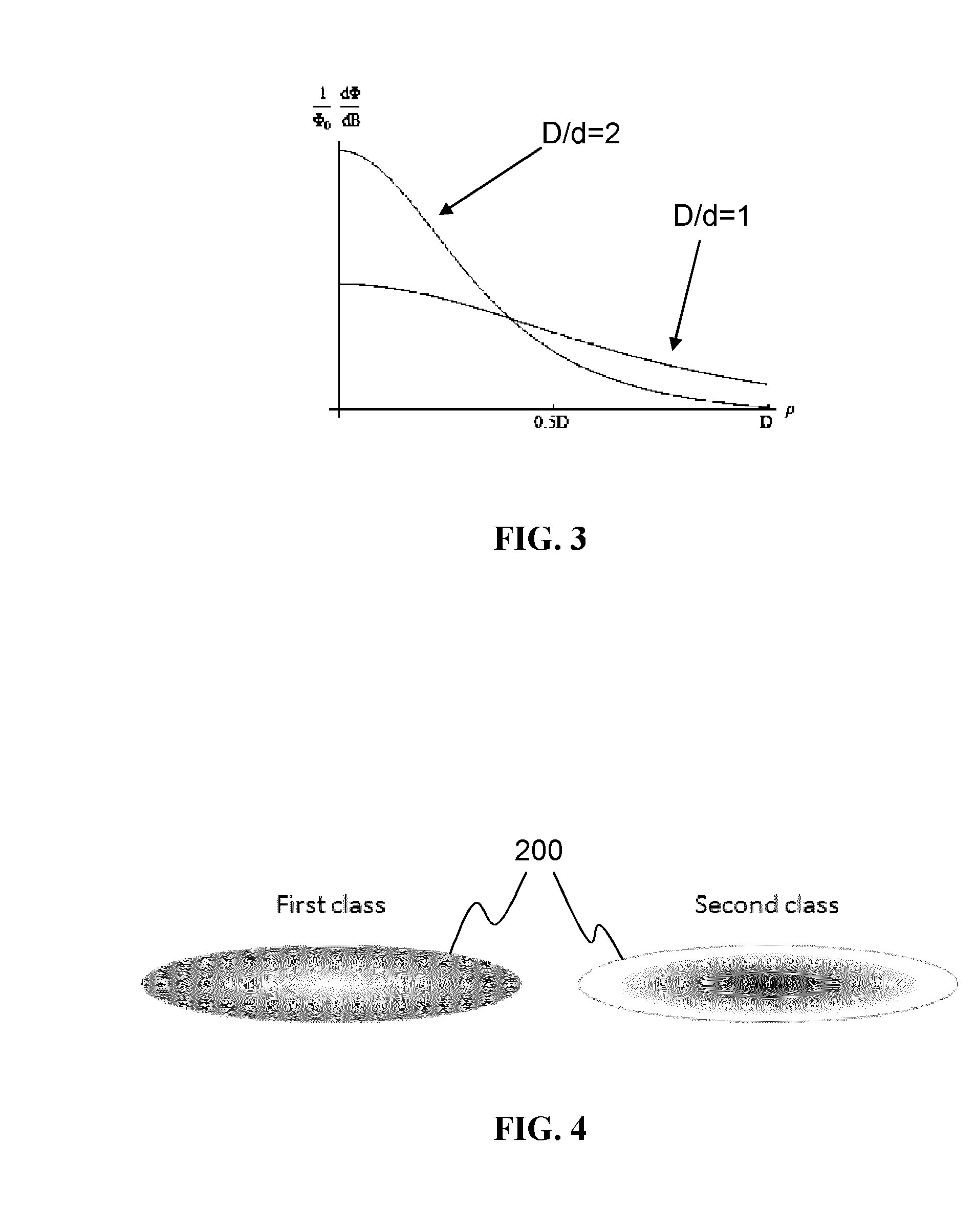
[0104]Embodiments of the present invention use a customized optical structure that makes an initially non-uniform exit window appear uniform within a range of polar angles. Such a structure can be realized by faceted optical elements—for example, a microstructure made using laser ablation or 3D printing in the form of an optical plate. This can potentially provide a relatively low-cost solution.

[0105]As explained in the introduction, the main disadvantage of the present LED lighting systems is their spottiness. The spottiness stems from the geometrical form-factor of the LED light sources. The present invention makes the luminaire exit window appear uniform within a certain range of angles where it is most advantageous to reduce the spottiness. Embodiments of the invention can redirect (diffuse) the light directly—without sending it back to the luminaire. This can allow much higher optical efficiency to be achieved.

[0106]In embodiments of the present invention, a diffuser comprises ...


PUM


Abstract

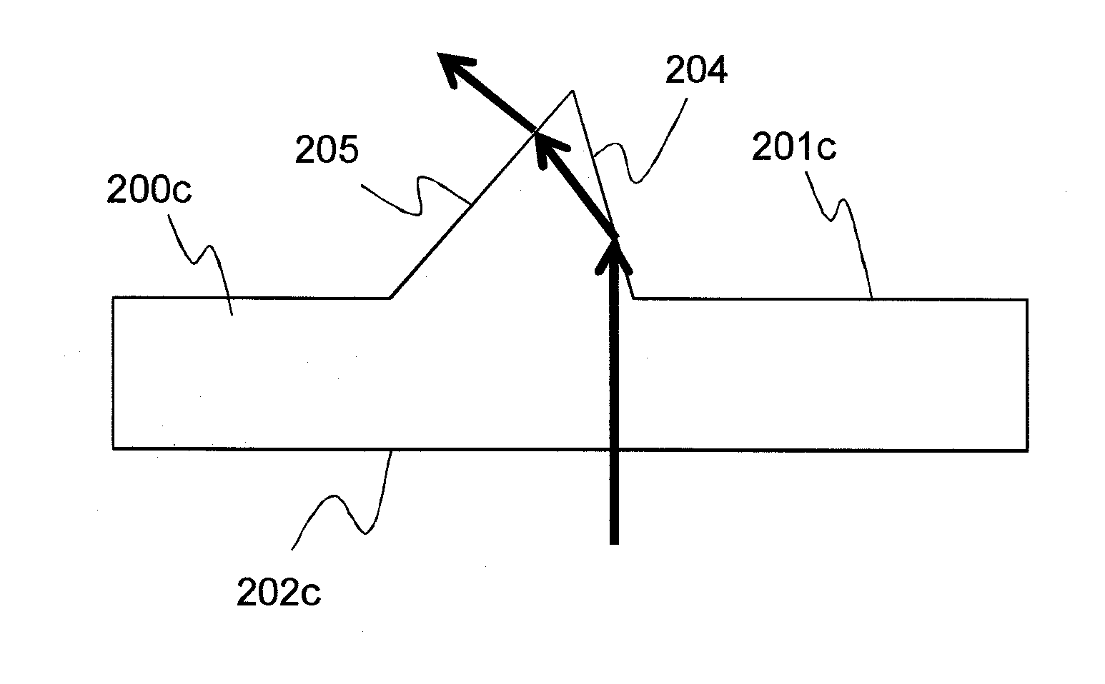
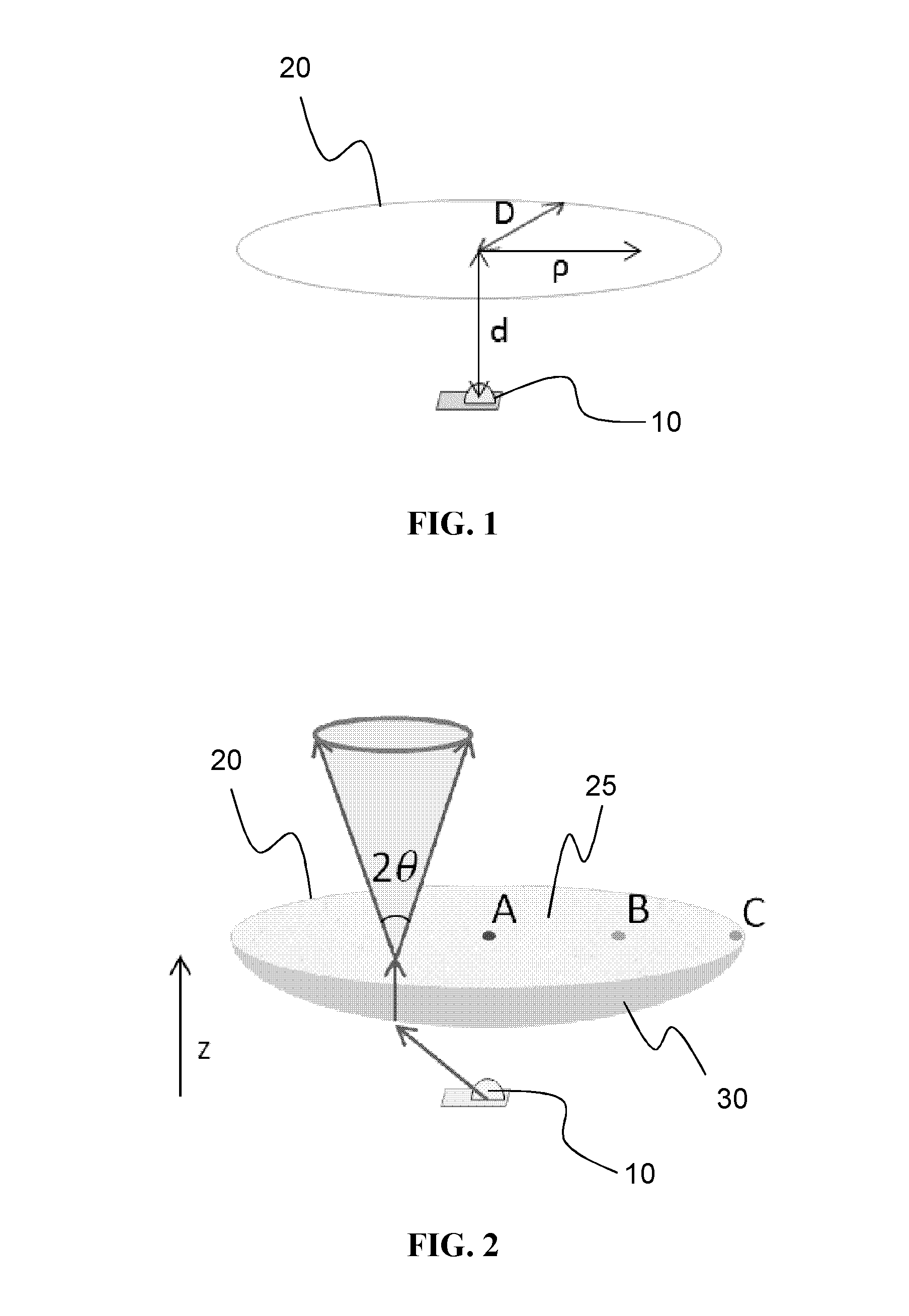
A luminaire comprising: a light source (10); an exit window (20) for light from the light source; and a diffuser (25; 200a; 200b; 200c; 200d) at the exit window for diffusing the light. The diffuser comprises a plurality of micro-optical elements (203a; 203b; 204, 205; 206, 207). Each micro-optical element is adapted to redirect light from the light source, so that the redirected light from each element emerges from the diffuser at a respective predetermined polar angle (Θ). The plurality of micro-optical elements comprise first micro-optical elements, which redirect light from the light source into a first range of polar angles, wherein the first optical elements occupy a greater proportion of the area of the diffuser in a first neighbourhood than in a second neighbourhood, and wherein the first neighbourhood receives less light from the light source than the second neighbourhood. Also provided is a method of designing and manufacturing a diffuser for such a luminaire.

Description

FIELD OF THE INVENTION[0001]This invention relates to luminaires in general and, in particular, to a diffuser for a luminaire. It is especially relevant for luminaires designed to be mounted on a ceiling, oriented substantially vertically downward.BACKGROUND OF THE INVENTION[0002]In lighting applications, the luminaires are required to provide a certain angular light distribution. Additionally, it is often desired that the luminaire exit window appears uniformly lit. That is, the luminous emittance of the exit window should be spatially uniform. This means that the luminous emittance Mv({right arrow over (ρ)}, θ0, φ0) at the angles θ0 and φ0 of the exit window should not depend on the position {right arrow over (ρ)} within that exit window. The luminous emittance at the angles θ0 and φ0 is obtained by integrating the luminance of the exit window Lv({right arrow over (ρ)}, θ0, φ0) over a solid angle. The solid angle corresponds to a human eye pupil size at some typical distance from ...

Claims


Application Information

Patent Timeline
Patent Type & Authority Applications(United States)
IPC IPC(8): F21V5/00G02B5/02
CPCF21V5/005G02B5/0231F21Y2101/02G02B5/0278G02B5/0263F21Y2101/00G02B19/0061
Inventor SEPKHANOV, RUSLAN AKHMEDOVICHKRIJN, MARCELLINUS PETRUS CAROLUS MICHAEL
Owner SIGNIFY HLDG BV
Learn More