

lighting device
A technology for lighting devices and lighting devices, applied to lighting devices, components of lighting devices, lighting and heating equipment, etc., can solve the problems of heavy lighting devices and difficult handling, and achieve less brightness unevenness and light weight Effect
- Summary
- Abstract
- Description
- Claims
- Application Information
AI Technical Summary
Problems solved by technology
Method used
Image

Examples
Embodiment approach 1
[0055] (Structure of lighting device)
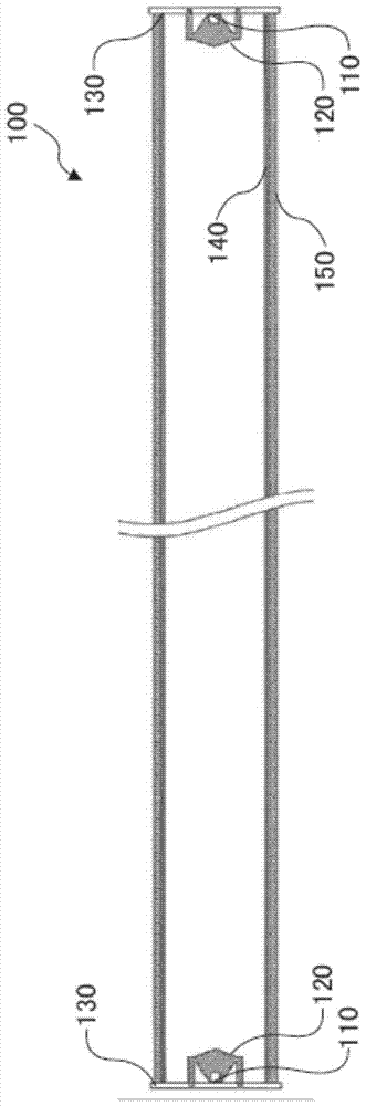
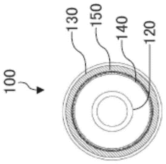
[0056] FIG. 2 is a cross-sectional view of the lighting device 100 according to the first embodiment. Figure 2A is a cross-sectional view of the long axis direction of the lighting device 100 (direction of the optical axis LA of the light emitting element 110), Figure 2B It is a cross-sectional view of the illuminating device 100 in the minor axis direction (the direction perpendicular to the optical axis LA of the light emitting element 110). image 3 yes Figure 2A Enlarged view of part of . Figure 4 yes Figure 2B Enlarged view of part of .
[0057] Figure 2 and image 3 As shown, the lighting device 100 includes a light emitting element 110 , a light beam control component 120 , a substrate 130 , a prism component 140 , and a diffusion component 150 . The light emitting element 110 and the light beam control member 120 constitute a light emitting device. The lighting device 100 includes one or more than two light emitting d...
Embodiment approach 2
[0094] The lighting device 300 according to Embodiment 2 of the present invention is different from the lighting device 100 according to Embodiment 1 in that it further includes a regular reflection member 370 . Therefore, the same reference numerals are assigned to the same components as those of the lighting device 100 according to Embodiment 1, and description thereof will be omitted.
[0095] (Structure of lighting device)
[0096] FIG. 7 is a cross-sectional view of a lighting device 300 according to Embodiment 2. As shown in FIG. Figure 7A is a partially enlarged cross-sectional view in the long axis direction (direction of the optical axis LA of the light emitting element 110), Figure 7B It is a cross-sectional view in the minor axis direction (direction perpendicular to the optical axis LA of the light emitting element 110).
[0097] In addition to the light emitting element 110 , the light beam control member 120 , the substrate 130 , the prism member 140 , the di...
Embodiment approach 3
[0118] The lighting device 500 according to the third embodiment of the present invention is different from the lighting devices 300 and 400 according to the second embodiment in that the specular reflection member 570 also functions as a holder for the light flux control member. Therefore, the same reference numerals are assigned to the same components as those of the lighting devices 300 and 400 according to Embodiment 2, and description thereof will be omitted.
[0119] (Structure of lighting device)
[0120] FIG. 11 is a cross-sectional view of a lighting device 500 according to Embodiment 3. As shown in FIG. Figure 11A is a partially enlarged cross-sectional view in the long axis direction (direction of the optical axis LA of the light emitting element 110), Figure 11B It is a cross-sectional view in the minor axis direction (direction perpendicular to the optical axis LA of the light emitting element 110).
[0121] As shown in FIG. 11 , the lighting device 500 includes...
PUM
 Abstract
Description
Claims
Application Information