

Stretch break method and product
a fiber and product technology, applied in the field of fiber conversion and spinning process, can solve the problems of slow early process, inability to compare to conventional spun yarn in strength, uniformity, cleanness, etc., and achieve the effect of minimizing static buildup in the fiber and minimizing the wrapping of loose ends
Inactive Publication Date: 2006-08-01
EI DU PONT DE NEMOURS & CO
View PDF29 Cites 7 Cited by
- Summary
- Abstract
- Description
- Claims
- Application Information
AI Technical Summary
Benefits of technology
[0027]gathering the loose filament ends in the break zone and adjacent the exit nip rolls and directing them toward the fiber core so the loose ends in all directions around the core are constrained to be within a distance from the center of the core of not greater than the distance of the center of the core from each respective end of the exit nip rolls for the break zone to minimize wrapping of the loose ends on the exit nip rolls.
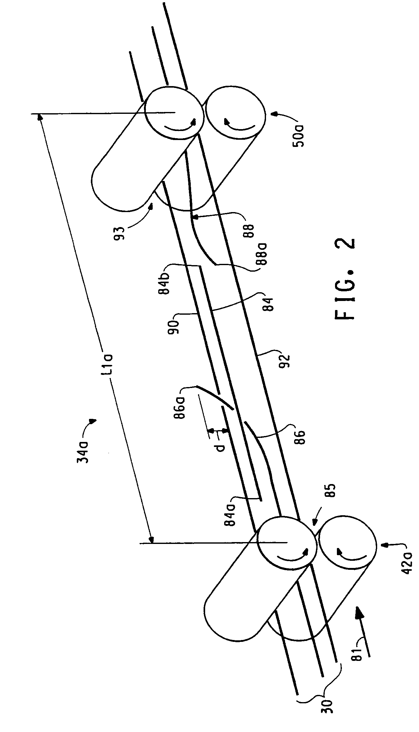
[0028]arranging the paths of the fiber through the functional zones in a stretch break process to be folded so when a path vector in a first functional zone is placed tail to tail with a path vector in a next sequential functional zone there is defined
Problems solved by technology
Such early processes were slow due to the inherent speed limitations of a true twisting device.
Such a product can be produced faster than true twisting, but is not comparable to conventional spun yarns in strength, cleanness, and uniformity.
There is a problem with the products produced by Adams et al in that the 1.5–20% of the discontinuous filaments exceeding 76 cm in length that are produced in the single stretch-breaking zone cause problems in further processing (primarily roll wraps) especially if a non-vertical process orientation is chosen.
There is also a problem with long filaments in the pr
Method used
View moreImage
Smart ImageViewing Examples

Examples
 PUM
| Property | Measurement | Unit |
|---|---|---|
| Length | aaaaa | aaaaa |
| Fraction | aaaaa | aaaaa |
| Fraction | aaaaa | aaaaa |
Abstract
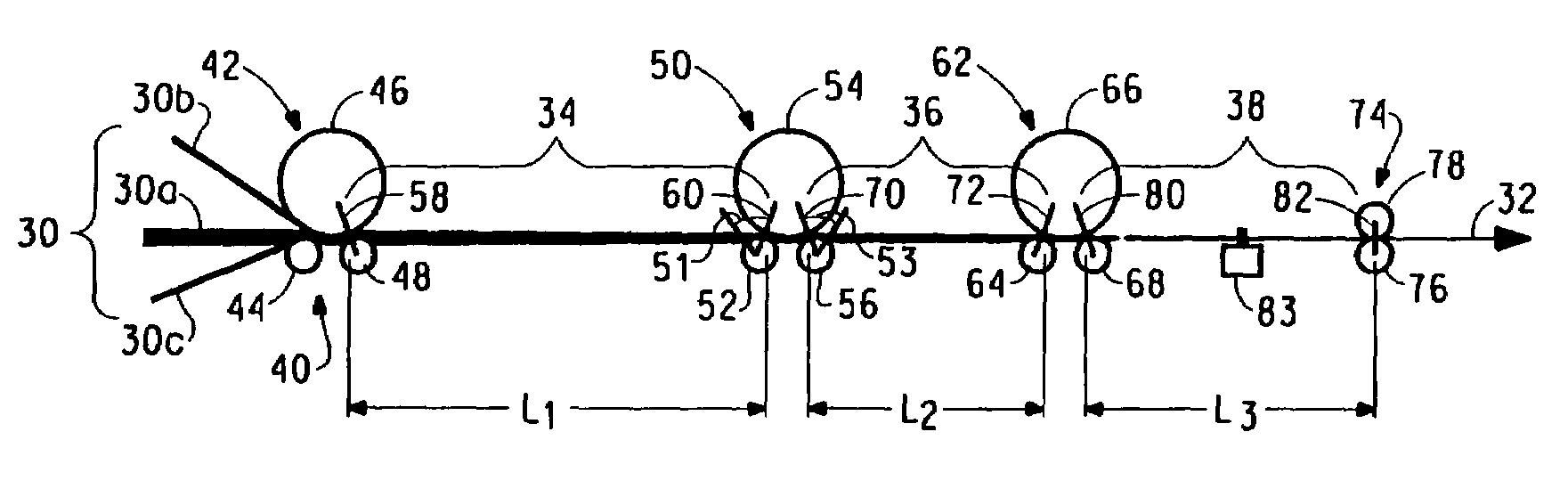
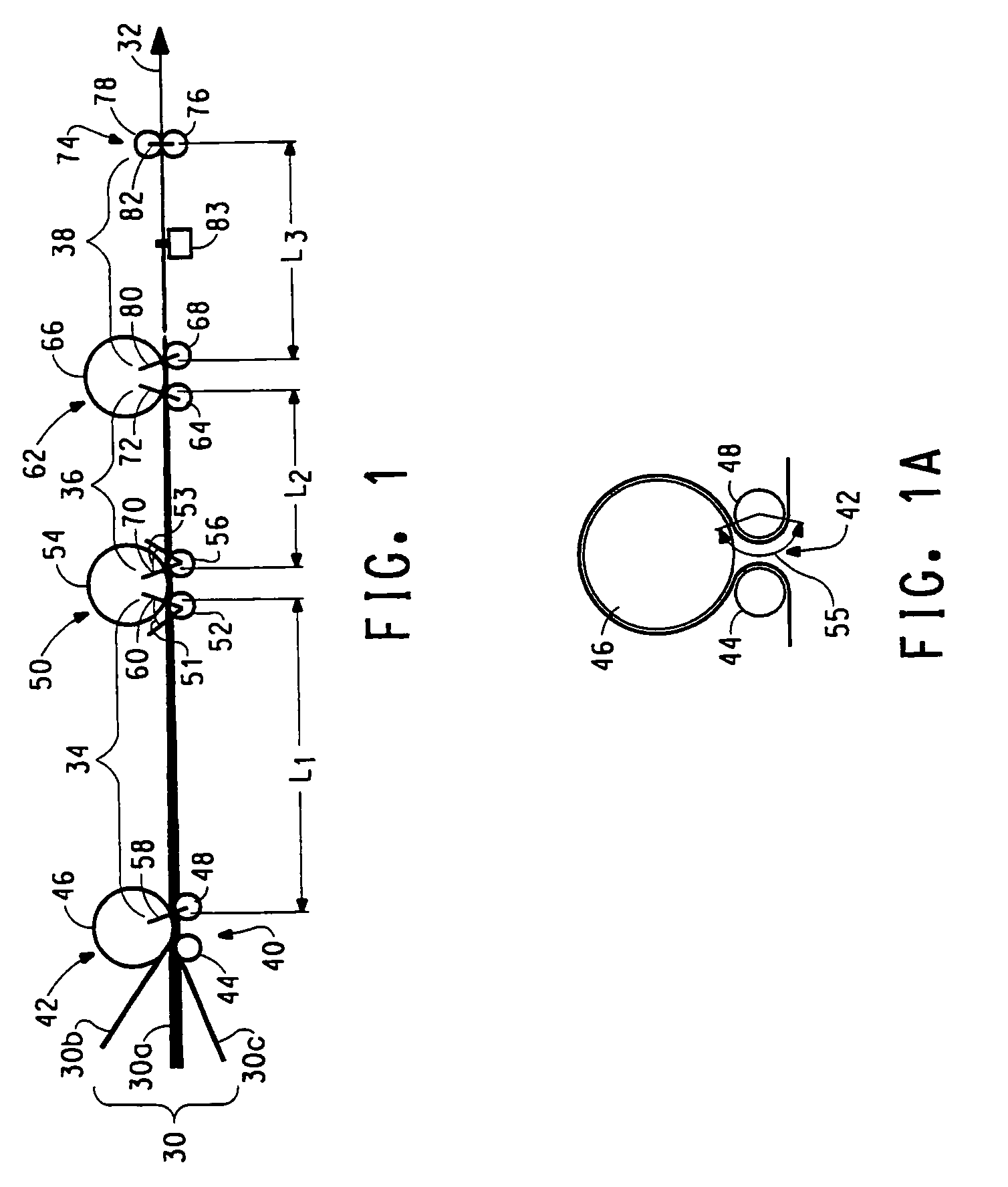
A method for stretch breaking fibers to produce a staple yarn and operating a staple fiber spinning machine that enables the production of a plurality of products of lot size smaller than a large denier tow product. The process includes at least two break zones and a consolidation zone downstream from a second break zone to form a staple yarn. The filaments are broken in a second break zone downstream from the first break zone by increasing the speed of the fiber fed into the process. The yarn includes discontinuous and, optionally, continuous filaments.
Description
[0001]This application is a continuation-in-part of U.S. Ser. No. 09 / 979,808, filed Nov. 21, 2001, which is incorporated in its entirety as a part hereof for all purposes.FIELD OF INVENTION[0002]This invention relates generally to a fiber conversion and spinning process, and more particularly concerns methods for stretch-breaking continuous filament fibers to form discontinuous filament fibers and consolidating these fibers into yarns.BACKGROUND[0003]Spun yarns of synthetic staple fibers have been produced by cutting continuous filaments into staple fibers, which are then assembled into individual yarn in the same manner as fibers of cotton or wool. A simpler direct spinning process is also used wherein parallel continuous filaments are stretch-broken and drafted between input rolls and delivery rolls in what is sometimes called a stretch break zone or a draft cutting zone to form a sliver of discontinuous fibers which is thereafter twisted to form a spun yarn as disclosed, for exam...
Claims
Login to View More Application Information
Patent Timeline
 IPC IPC(8): D01F6/00D01G1/08D02G3/04
CPCD01G1/08D02G3/045Y10T428/2929Y10T428/2924Y10T428/2904
InventorSIMMONDS, GLENCORCORAN, BILLWALKER, BILL
OwnerEI DU PONT DE NEMOURS & CO