
Device for automatically actuating a door, in particular a vertical door

a technology of automatic activation and door, which is applied in the direction of door/window protective devices, counting objects on conveyors, instruments, etc., can solve the problems of insufficient sensitivity of sensors operating according to the doppler principle for the region of the approach area located near the opening plane, and the addition of equipment to the cost of doors and windows, etc., to achieve a high degree of safety

Inactive Publication Date: 2006-08-01
EFAFLEX TOR & SICHERHEITSSYSTEME GMBH & CO KG
View PDF10 Cites 15 Cited by
  • Summary
  • Abstract
  • Description
  • Claims
  • Application Information

AI Technical Summary

Benefits of technology

[0012]The invention is intended to achieve the object of configuring a device for automatically activating a door, in particular a lifting door, which has an essentially vertical opening plane, an inner side and an outer side, and approach areas which are near to the floor and are respectively located on the inner side and on the outer side, in such a way that a high degree of safety is achieved both against damage to obstructing objects or injury to persons impacting against the closing door as well as against damage to the closing door by obstructing objects without a plurality of different monitor systems having to be provided.
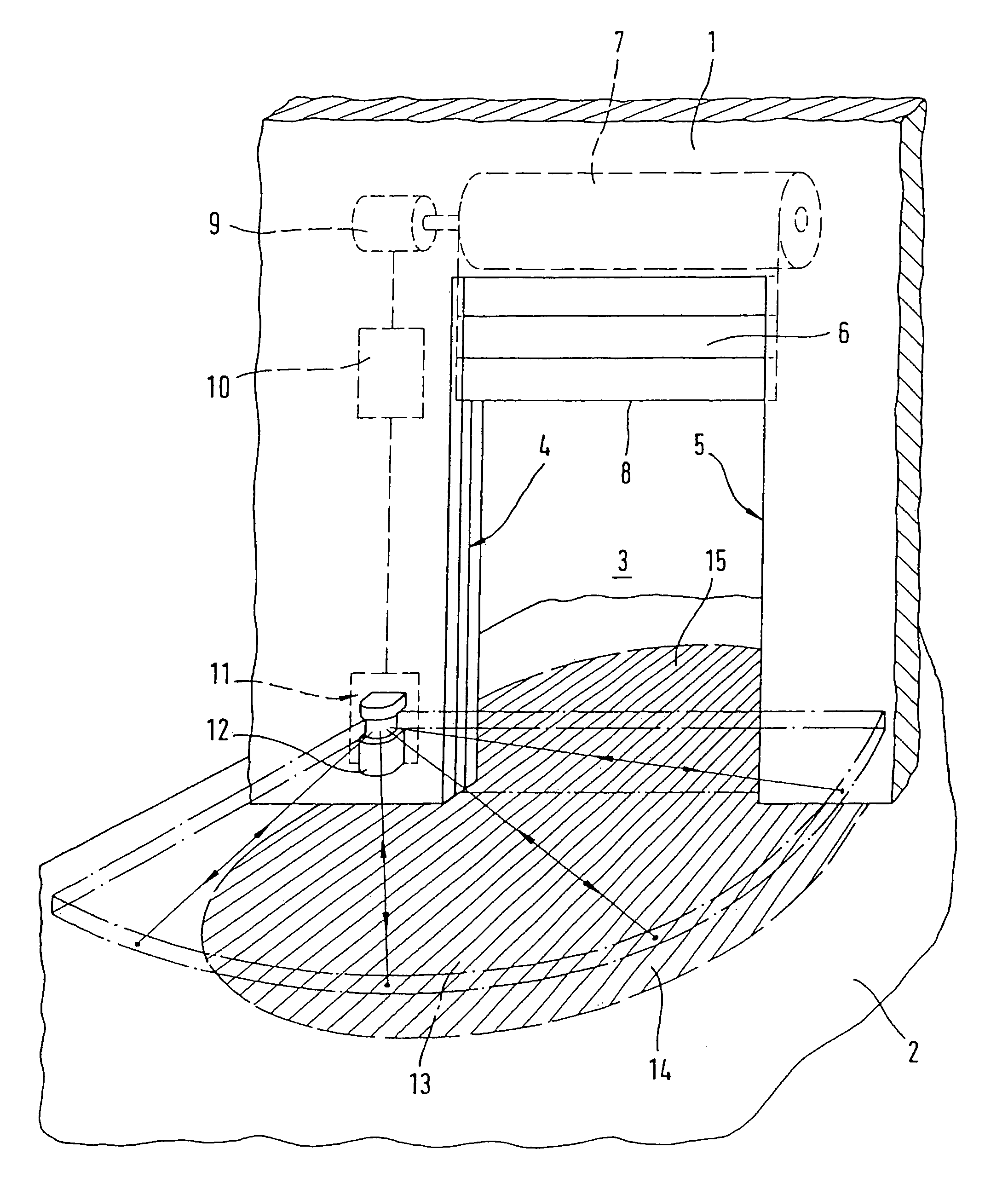
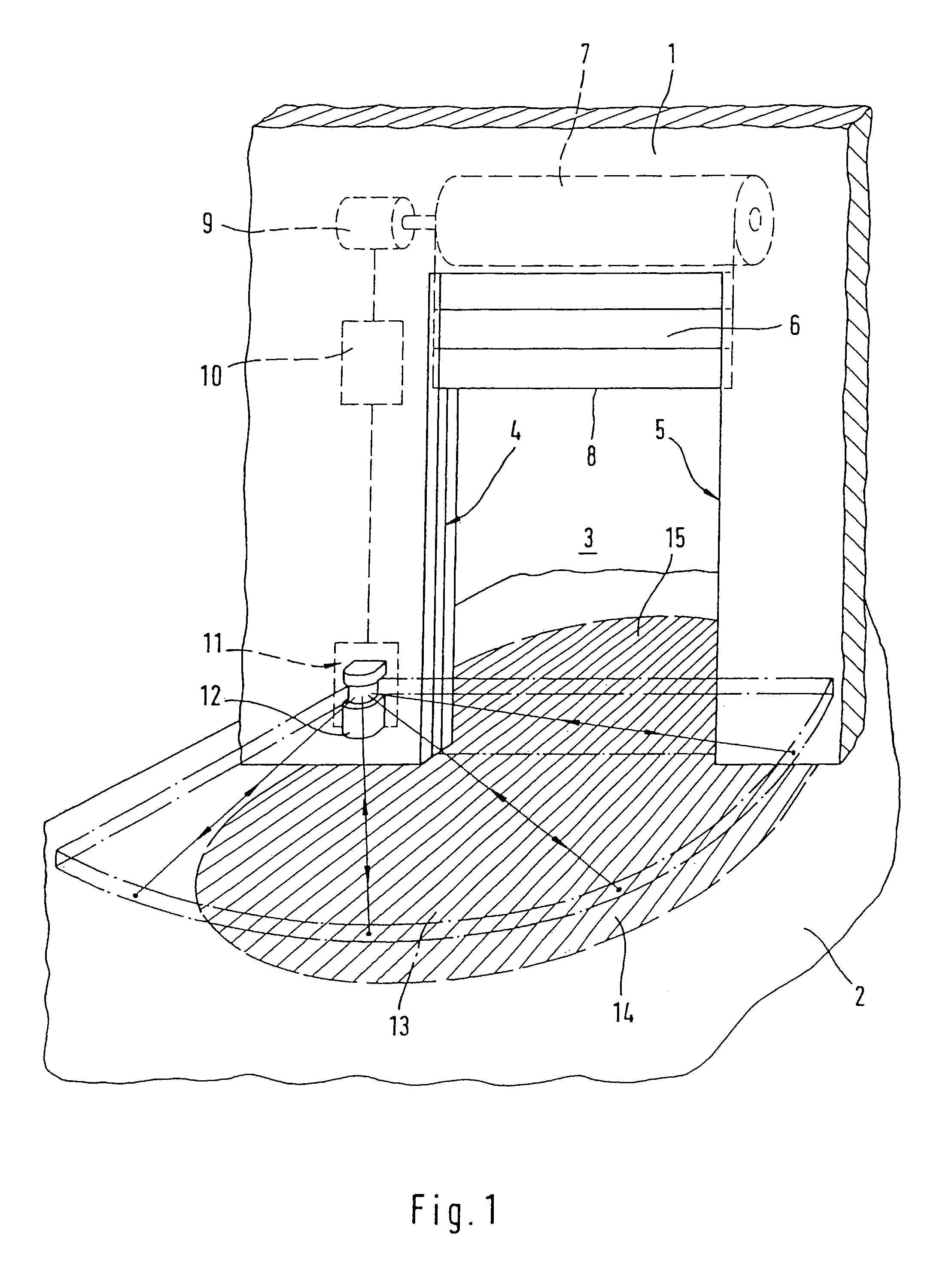
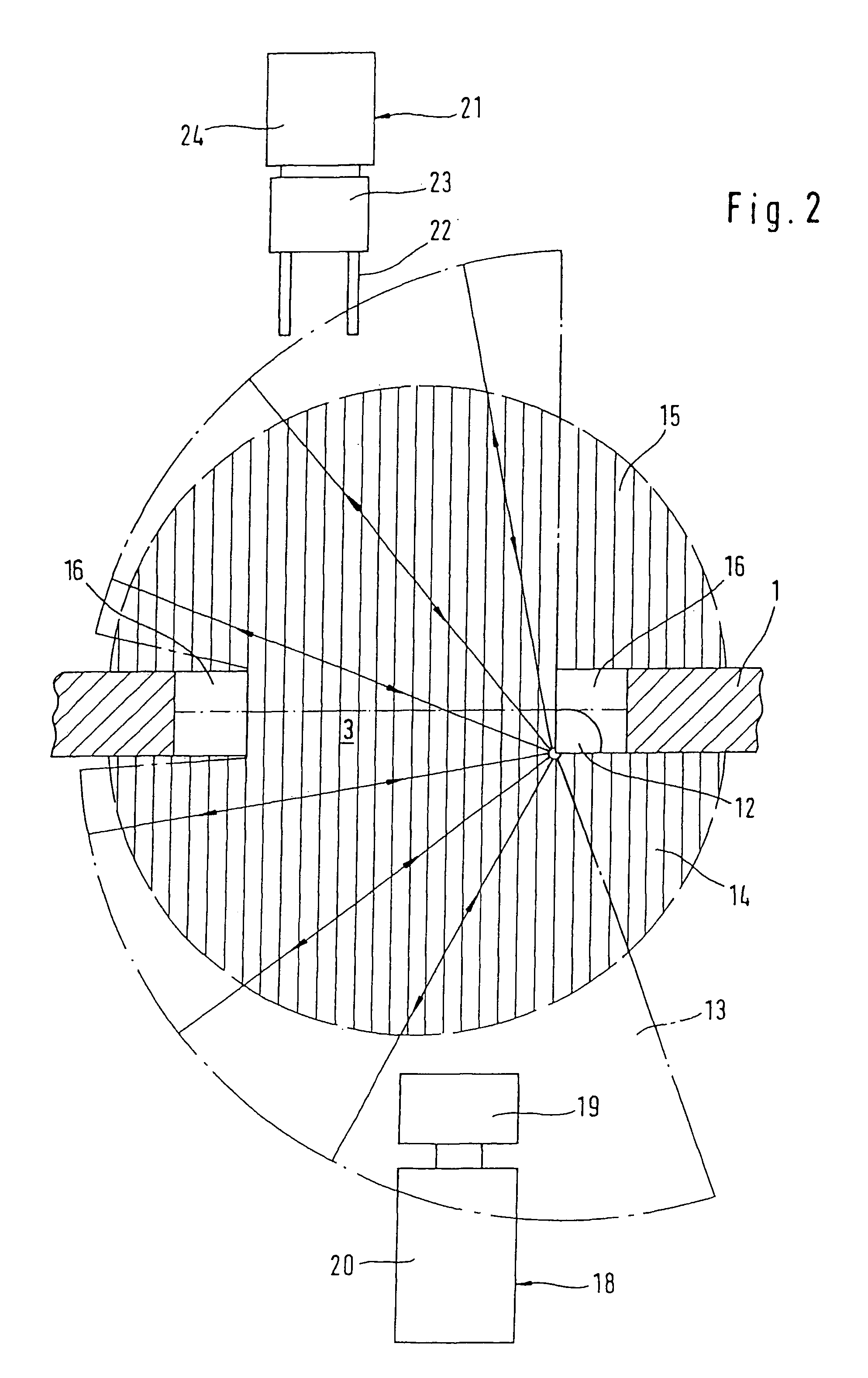
[0016]The invention is based on the idea that obstructing objects or persons which are about to penetrate the part of the opening plane which is not yet covered by a closing door, and are thus at risk of being struck by the closing edge of the door, being jammed in it or of damaging the door, are in all cases supported on the ground in one of the approach areas and therefore penetrate the aforesaid part of the opening plane of the closing door, and in all cases infringe the horizontal monitored region which is in the form of the horizontal fan emitted by the scanning detector and is superimposed on the respective approach area at a short vertical distance, in such a way that, given appropriate dimensioning of this horizontal fan, there is no longer any need for a device according to the invention to have a curtain-like monitored region extending across the door opening. Therefore, a highly simplified design of the entire device is obtained together with increased protection against injuries to persons or damage to objects or to the closing door.

Problems solved by technology

In these known systems, the proximity sensor which is to be provided in addition to the light curtain which monitors the door opening plane and which monitors approach areas on the inner side of the door or outer side of the door entails additional expenditure on equipment.
Finally, movement sensors which are mounted above the opening of the door have the disadvantage that, at a short distance in front of the opening plane, detector beams of the proximity sensor are directed very steeply downward onto the approach area to be monitored and therefore a horizontal speed of an obstructing object which is to be sensed or of a person which is to be sensed only has a very small speed component in the direction of the detector beam, such that movement sensors which operate according to the Doppler principle often have an inadequate sensitivity for the region of the approach area which is located near to the opening plane.

Method used


Image

  • Device for automatically actuating a door, in particular a vertical door
  • Device for automatically actuating a door, in particular a vertical door
  • Device for automatically actuating a door, in particular a vertical door

Examples


Embodiment Construction

[0027]The scanning detector which is mentioned in the following statement is preferably a laser radar scanning detector. The direction of the finely focused scanning beam of the scanning detector can be determined by the directional beam of the transmission and reception device.

[0028]FIG. 1 indicates a part 1 of a building which projects from the plane 2 of the floor and is penetrated by a door opening 3. At the lateral delimitations 4 and 5 of the door opening 3 there are door guiding and supporting structures, for example guide rails, in which a laminated roller door 6 is guided, which can be wound onto a roller 7 in order to open the door, or unwound from the roller 7 in order to close the door, with the result that the closing edge 8 of the roller door 6 ultimately drops as far as the plane 2 of the floor. The roller door 6 is moved automatically by means of a door drive 9 which is coupled to a control device 10 to which control signals are fed (in a fashion which is not illustr...


PUM


Abstract

The invention relates to a device for automatically actuating a door, in particular a vertical door, which aims to replace to a great extent known signal generation devices or control signal sensors for opening the door or for the security monitoring of the closing motion of the door. This is achieved by a detector of a security system, which is configured as a scanner detector and operates according to reflective principles, for monitoring an area by allocation to one of the ground level aprons of the door, said detector being mounted in the vicinity of a lateral border of the door opening, at a height, which is adjusted to the maximum height of objects supported on the relevant apron that are not to be registered as obstacles. The scanning beam of said detector scans a horizontal fan-shaped area, which covers the relevant apron and has a low vertical depth, determined by the depth of the scanning beam, as the monitoring area. The radial dimension of said fan-shaped area, which is determined by the maximum measuring range of the scanning detector, is selected according to the size of the relevant apron.

Description

[0001]This application is the US national phase of international application PCT / EP03 / 00809 filed 27 Jan. 2004, which designated the US and claims priority to DE Application No. 102 03 145.2 filed 28 Jan. 2002. The entire contents of these applications are incorporated herein by reference.BACKGROUND OF THE INVENTION[0002]1. Field of the Invention[0003]The invention relates to a device for automatically activating a door, in particular a lifting door, which has an essentially vertical opening plane, an inner side and an outer side, and approach areas which are level with the floor and are respectively located on the inner side and on the outer side.[0004]2. Description of Related Art[0005]It is generally known that with automatically activated doors it is necessary to take safety precautions to prevent obstructing objects or persons who are located in the door opening from being damaged or injured when the door is automatically closed.[0006]For this purpose, it has been known to arra...

Claims


Application Information

Patent Timeline
Patent Type & Authority Patents(United States)
IPC IPC(8): G06M7/00E05F15/43E06B9/58E06B9/88
CPCE06B9/58E06B9/88E05F15/43E05F2015/434E05Y2900/00E06B2009/587E05Y2900/106B66B13/26B66B13/06
Inventor REJC, PETRA
Owner EFAFLEX TOR & SICHERHEITSSYSTEME GMBH & CO KG
Learn More