Energy harvesting circuit

a technology of energy harvesting circuit and energy harvesting circuit, which is applied in the direction of secondary cell servicing/maintenance, electrochemical generators, instruments, etc., can solve the problem that energy harvesting circuits cannot efficiently harvest rf energy at frequencies, and achieve the effect of maximizing the harvesting of rf energy

Active Publication Date: 2006-08-01
UNIVERSITY OF PITTSBURGH
View PDF7 Cites 340 Cited by
  • Summary
  • Abstract
  • Description
  • Claims
  • Application Information

AI Technical Summary

Benefits of technology

[0017]This energy harvesting circuit would provide mobile power storage devices with a means to select the ambient RF that can provide the maximum amount of energy for harvesting. This energy harvesting circuit can be used to energize power storage devices including capacitors and batteries, for example, that are used in electronic devices such as cell phones, cameras, and PDAs. Maximizing energy harvesting using a broadband antenna would enable a device with power storage devices to move from location to location without manual tuning of the circuit.
[0020]Additionally, the circuit can be an antenna array consisting of multiple broadband antennae in the same space each tuned to a specific portion of the frequency spectrum in order to maximize the harvest of RF energy from a given RF spectrum with multiple antennae in the same physical space.

Problems solved by technology

A problem with the prior art is that the energy harvesting circuits cannot efficiently harvest RF energy at frequencies outside the design specific frequency of the antenna.
However, the antenna for efficient energy harvesting requires characteristics that are different from those of a communications antenna.

Method used


Image

  • Energy harvesting circuit
  • Energy harvesting circuit
  • Energy harvesting circuit

Examples


example

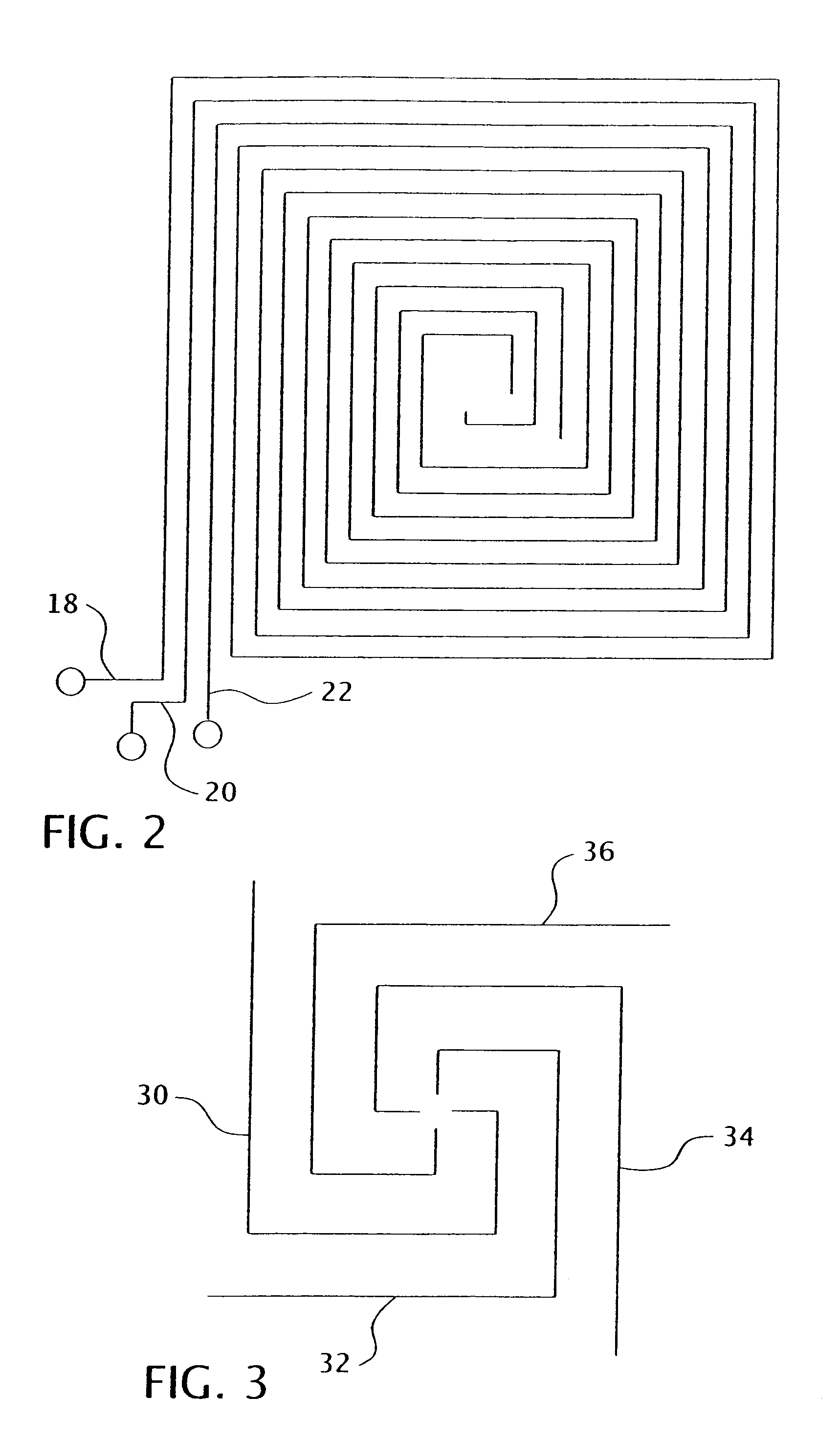
[0078]Multiple antennae are advantageous in situations of low ambient energy where multiple harvesting circuits can be connected in series in order to increase the DC voltage resulting from the harvested, energy. The three antennae 18, 20, 22 of the embodiment of FIG. 2 can be easily connected to the rectifying circuitry from the connection points. FIG. 5 shows a tuning circuit24A. 24B, 24C and a rectifier / charge pump 26A, 26B, 26C connected to each of the three antennae 18, 20, 22 as described elsewhere herein. FIG. 6 shows each of the three antennae 18, 20, 22 connected to an RF combiner or balun 28 and a rectifier / charge pump 29 as described elsewhere herein. Other configurations are possible, however, the connection point should preferably be at the outside of the rectangular configuration. This is a line feed mechanism. Connecting at the center (probe feed) has been shown to be a poor choice for maximum energy harvesting.

[0079]In addition, it is desirable to design the multiple...


PUM

PropertyMeasurementUnit
frequenciesaaaaaaaaaa

Abstract

A station having a means for receipt of ambient energy from the environment and energizing power storage devices of objects of interest comprising one or more antennae and circuitry for converting said ambient energy into DC power for energizing said power storage devices. The circuitry for converting the ambient energy into DC power may include a rectifier / charge pump. The antenna of the station is tuned to maximize DC energy at the output of the rectifier / charge pump. The station can be used to energize power storage devices including capacitors and batteries that are used in electronic devices, such as cell phones, cameras, PDAs. Various antenna constructions may be employed.

Description

CROSS-REFERENCE[0001]This application claims the benefit of U.S. Provisional Application Ser. No. 60 / 515,393 entitled “ENERGY HARVESTING CIRCUIT” filed Oct. 29, 2003.BACKGROUND OF THE INVENTION[0002]1. Field of the Invention[0003]The harvesting of Radio Frequency (RF) energy is extremely important for Radio Frequency Identification (RFID), security monitoring and remote sensing. Numerous uses such as some harvesting devices may be tuned to a specific frequency (RFID), while others take advantage of the ambient energy (remote sensing) and others simply sense frequencies for security purposes.[0004]2. Description of the Prior Art[0005]Recharging devices using an RF electromagnetic field radiated into free space have been described. U.S. Pat. No. 6,127,799 entitled, “Method and Apparatus for Wireless Powering and Recharging”. This patent discloses a battery charging arrangement in which a rechargeable charge storage device is placed in an RF or microwave radiation field. In one aspect ...

Claims


Application Information

Patent Timeline
Patent Type & Authority Patents(United States)
IPC IPC(8): H01M10/44H01Q1/26H02N
CPCH02J17/00H01M10/44H02J50/001Y02E60/10H02J50/27H02J50/40H01Q1/248
Inventor MICKLE, MARLIN H.CAPELLI, CHRISTOPHER C.SWIFT, HAROLD
Owner UNIVERSITY OF PITTSBURGH
Why Eureka
Try Eureka