Liquid crystal display device

a liquid crystal display and display state technology, applied in the field of liquid crystal display devices, can solve the problems of poor effect of increasing the fall response speed, inability to effectively enhance the high-band enhancement of input image signals, and poor effect of improving the response characteristics at a fall

Inactive Publication Date: 2006-08-01
SHARP KK
View PDF21 Cites 25 Cited by
  • Summary
  • Abstract
  • Description
  • Claims
  • Application Information

AI Technical Summary

Benefits of technology

[0018]A liquid crystal display device according to a first aspect of the present invention includes: a liquid crystal panel including a liquid crystal layer and an electrode for applying a voltage to the liquid crystal layer; and a driving circuit for supplying a driving voltage to the liquid crystal panel, wherein the liquid crystal panel exhibits, in its voltage-transmittance characteristics, an extreme transmittance at a voltage equal to or lower than a lowest...

Problems solved by technology

However, the effect of improving the response characteristics at a fall (a change to the display state corresponding to a decrease in voltage applied to the liquid crystal layer) is relatively poor.
Therefore, the effect of increasing the fall response speed is poor even if the input image signal S(t) is emphasized.
Moreover, the driving method disclosed in the aforemen...

Method used


Image

  • Liquid crystal display device
  • Liquid crystal display device
  • Liquid crystal display device

Examples


embodiment 1

[0057]Hereinafter, an embodiment of an LCD according to a first aspect of the present invention will be described with reference to the accompanying drawings. The present embodiment is herein exemplarily described regarding an NW mode LCD. However, the LCD according to the first aspect of the present invention is not limited to the NW mode LCD.

[0058]Functions of the LCD according to the first aspect of the present invention will now be described.

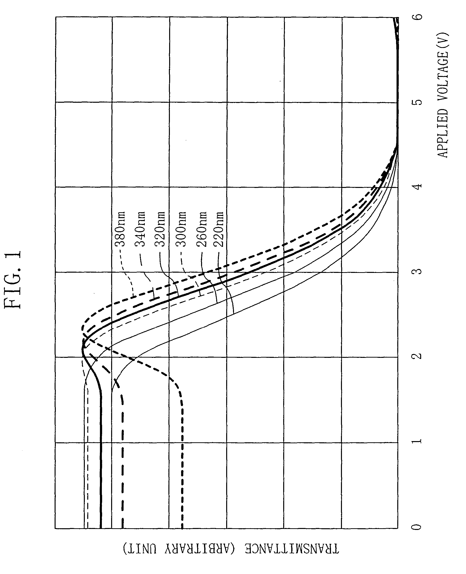
[0059]A liquid crystal panel of the LCD according to the first aspect of the present invention exhibits, in its V-T characteristics, an extreme transmittance at a voltage equal to or lower than the lowest gray-level voltage. An overshoot gray-level voltage is applied to the liquid crystal panel. Note that, the LCD is generally an AC-drive device, but the V-T characteristics thereof represent the relation between the absolute value of the voltage applied to the liquid crystal layer and the transmittance, based on a potential of the counter el...

embodiment 2

[0160]Hereinafter, an embodiment of the LCD according to a second aspect of the present invention will be described with reference to the drawings. However, the LCD according to the second aspect of the present invention is not limited to the following embodiment.

[0161]FIG. 12 schematically shows the structure of the LCD according to the present embodiment. Note that, in the following embodiment, an interlace-driven LCD in which a single field corresponds to a single vertical period is exemplarily described.

[0162]In the case where the gray-level voltage Vg is referred to in the order of magnitude, the gray-level voltage is denoted with Vv. For example, for 64-gray-scale display from zero (black) to 63 (white) gray levels, the gray-level voltage having the lowest value is denoted with Vv0, and the gray-level voltage having the highest value is denoted with Vv63. In the case of the NW mode LCD, Vv0 is a voltage for displaying the highest gray level (63 gray level), and Vv63 is a volta...

embodiment 3

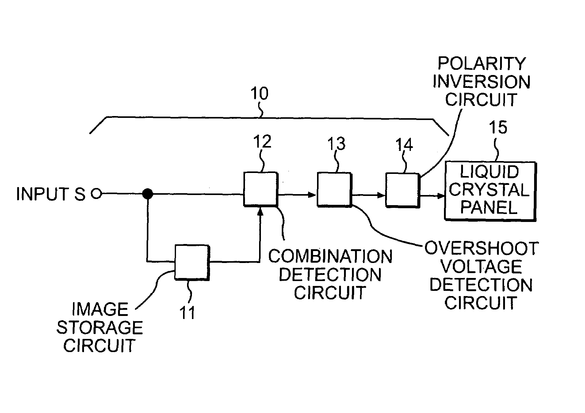
[0222]An LCD of the third embodiment is a TFT-type LCD as shown in FIG. 12. More specifically, the LCD of the third embodiment is a NW mode display device including the liquid crystal panel 20 shown in FIG. 7 and the driving circuit 10 shown in FIG. 4. This LCD will be described with reference to FIGS. 4, 7 and 12.

[0223]The TFT substrate 21 and CF substrate 22 forming the TFT-type liquid crystal panel are made according to a known method. The capacitance of a single storage capacitor Cs of the TFT substrate 21 is, e.g., 0.200 pF. An alignment film (which is formed from, e.g., polyimide or polyvinyl alcohol) is formed on each of the respective surfaces of the substrates 21 and 22 that face the liquid crystal layer 27. Then, the surface of each alignment film is rubbed in one direction.

[0224]The TFT substrate 21 and CF substrate 22 thus obtained are laminated with each other such that their respective rubbing directions are in anti-parallel with each other. Then, a nematic liquid crys...


PUM


Abstract

A liquid crystal (LC) display device includes a LC panel and a driving circuit. The LC panel exhibits, in its voltage-transmittance characteristics, an extreme transmittance at a voltage equal to or lower than a lowest gray-level voltage. The driving circuit supplies to the LC panel a predetermined driving voltage overshooting a gray-level voltage corresponding to an input image signal of a current vertical period, according to a combination of an input image signal of an immediately preceding vertical period and the input image signal of the current vertical period.

Description

[0001]This application is a continuation of U.S. patent application Ser. No. 09 / 820,021, filed 28 Mar. 2001, now abandoned entitled LIQUID CRYSTAL DISPLAY DEVICE.BACKGROUND OF THE INVENTION[0002]1. Field of the Invention[0003]The present invention generally relates to a liquid crystal display device (LCD). More particularly, the present invention relates to an LCD preferably used for moving picture display.[0004]2. Description of the Background Art[0005]The LCDs are used for, e.g., personal computers, word processors, amusement equipments, television sets, and the like. Improvement in response characteristics of the LCDs has been studied for high-quality moving picture display.[0006]Japanese Laid-Open Publication No. 4-288589 discloses an LCD having an increased response speed for intermediate-gray-scale display in order to reduce a residual image. In this LCD, an input image signal having its high-band components pre-enhanced is supplied to a liquid crystal display section so that ...

Claims


Application Information

Patent Timeline
IPC IPC(8): G09G3/34G02F1/1333G02F1/1343G09G5/10G02F1/133G09G3/36
CPCG09G3/36G09G3/3648G09G2340/16G09G2320/02G09G2320/0252G09G2310/06G02F1/133
Inventor ADACHI, TAKAKOSHIOMI, MAKOTO
Owner SHARP KK
Why Eureka
Try Eureka