
Method and apparatus for obtaining high dynamic range images

a high-dynamic range, image technology, applied in the direction of color television details, color signal processing circuits, television systems, etc., can solve the problems of insufficient capture of insufficient dynamic range of known image sensing devices, and inability to capture the fine details of most real-life scenes. to achieve the effect of high-dynamic range images

Inactive Publication Date: 2006-08-01
THE TRUSTEES OF COLUMBIA UNIV IN THE CITY OF NEW YORK +1
View PDF21 Cites 123 Cited by
  • Summary
  • Abstract
  • Description
  • Claims
  • Application Information

AI Technical Summary

Benefits of technology

Enables the capture of high dynamic range images with improved spatial resolution, overcoming limitations of prior techniques by using a single low dynamic range sensor with spatially varying sensitivity, allowing for efficient and compact imaging systems.

Problems solved by technology

By contrast, known image sensing devices have very limited dynamic ranges.
In the case of grey-scale images, 8-bits allows only 256 discrete grey-scale levels, which is not sufficient to capture the fine details of most real life scenes.
However, known temporal exposure variation techniques all have the fundamental problem in that changes in the scene may take place during the sequential image capture at different exposures.
The multiple image sensor techniques have the drawback in that they require high precision optics and a plurality of image sensors so that it is difficult to build compact and inexpensive imaging systems using these techniques.
However, known spatial exposure variation techniques for high dynamic range imaging have the drawback of providing lower spatial resolution (typically a factor of two lower in the vertical direction) than the resolution of ordinary image sensors having the same number of light-sensing elements.

Method used


Image

  • Method and apparatus for obtaining high dynamic range images
  • Method and apparatus for obtaining high dynamic range images
  • Method and apparatus for obtaining high dynamic range images

Examples


Embodiment Construction

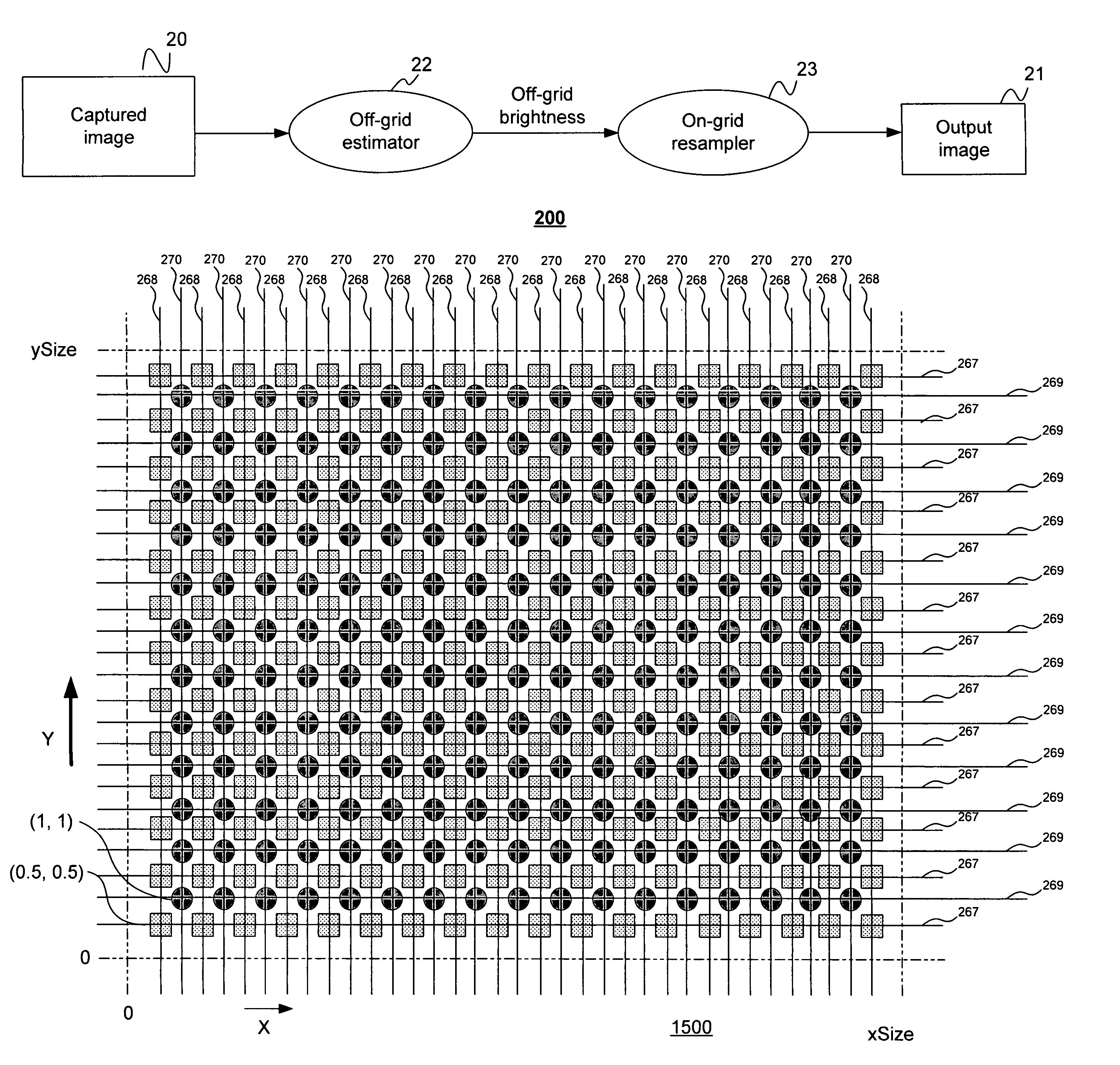
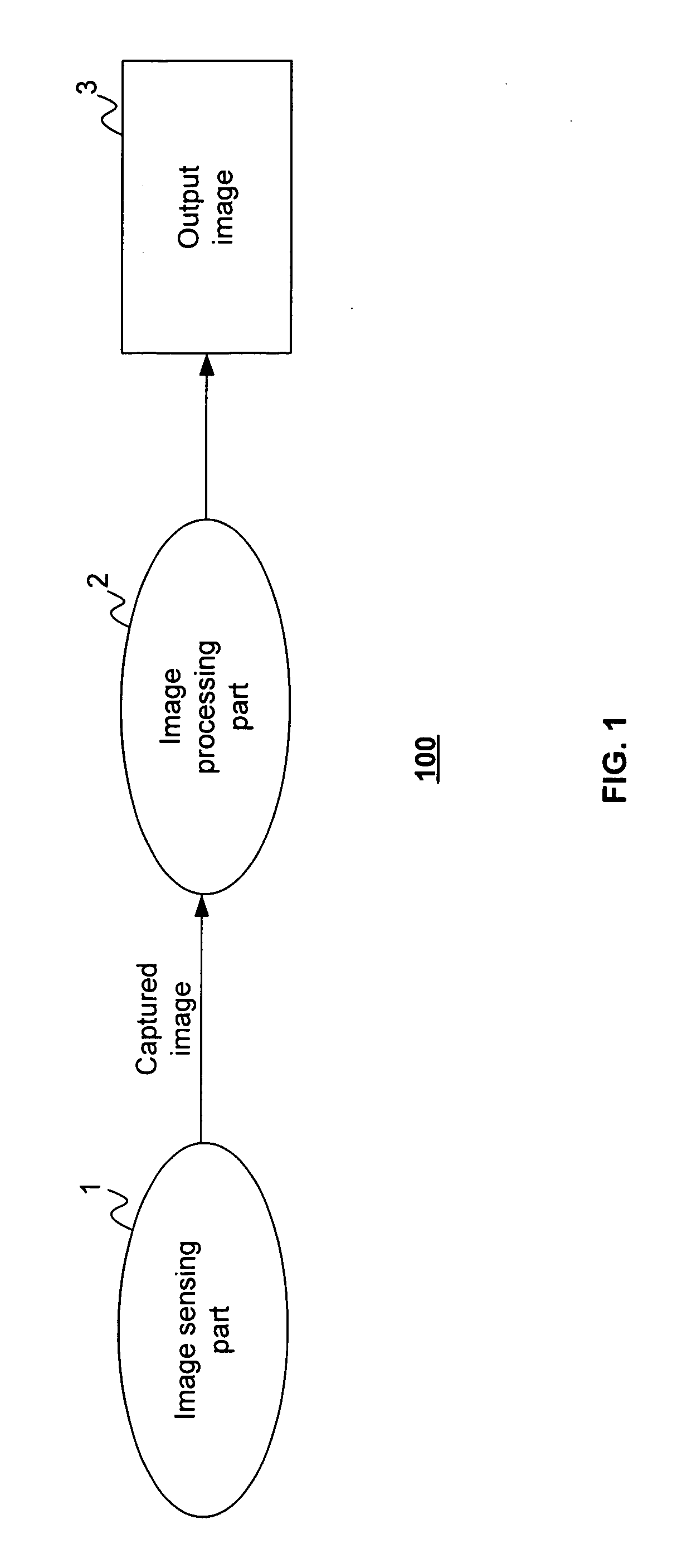
[0084]Referring to FIG. 1, there is shown a data flow diagram 100 of a system for capturing relatively high dynamic range images using a relatively low dynamic range image sensor in accordance with the present invention. The system has an image sensing part 1 that includes a relatively low dynamic range image sensor (not shown in FIG. 1) having a multiplicity of light-sensing elements in an array (not shown). The term “light” as used in the specification and claims shall mean electromagnetic radiation whose wavelength may be anywhere in the spectrum from the far infrared to x-rays. The array of light-sensing elements of the image sensor may have any arrangement, including without limitation rectangular, linear, circular and hexagonal grids, and the light-sensing elements in the array need not be uniformly disposed. The array of light-sensing elements has a predetermined spatially varying sensitivity pattern to incident light, and each light-sensing element of the image sensor produc...


PUM


Abstract

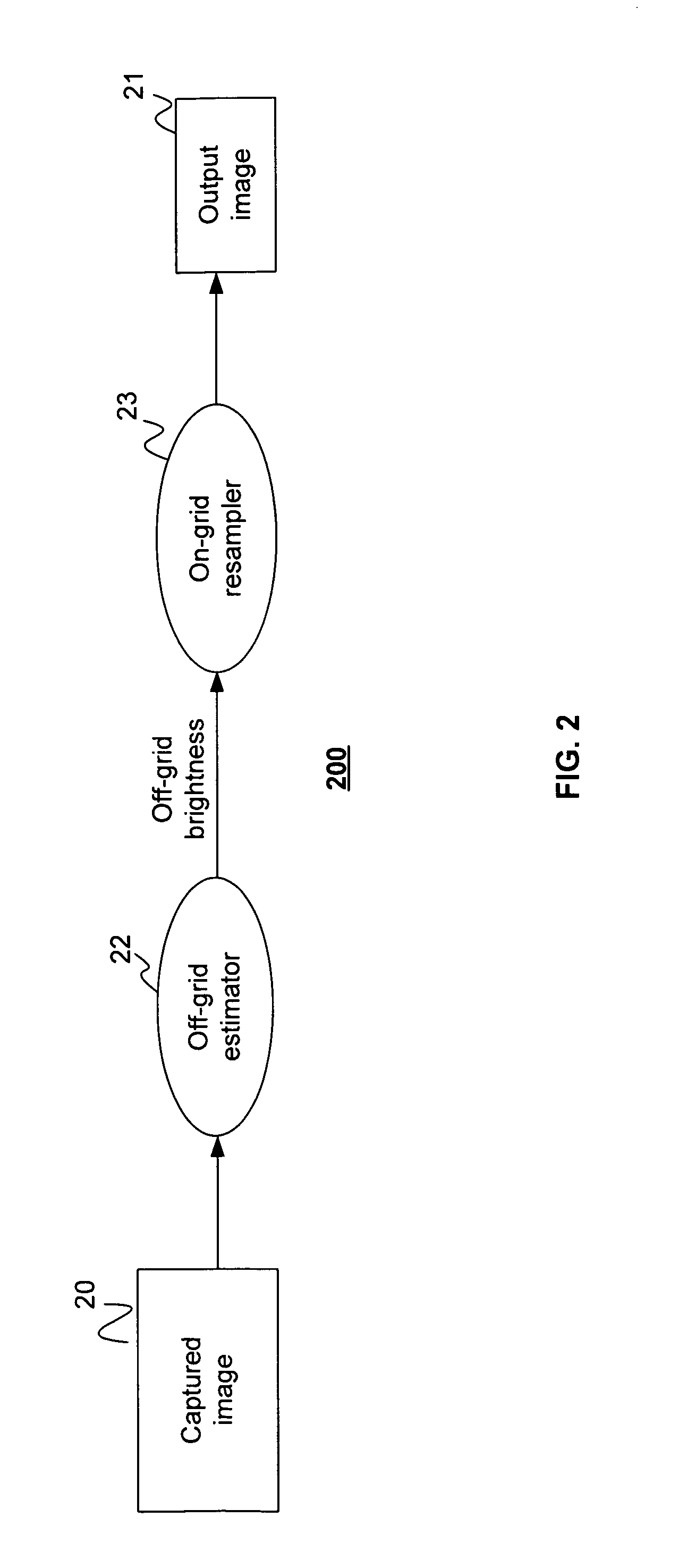
Disclosed are method and apparatus for obtaining relatively high dynamic range images using a relatively low dynamic range image sensor without significant loss of resolution. The image sensor has an array of light-sensing elements with different sensitivity levels in accordance with a predetermined spatially varying sensitivity pattern for the array of light-sensing elements. An image of a scene is captured with the image sensor and stored as brightness values at respective pixel positions in a linear or two-dimensional uniform grid. The brightness values of the captured image at the pixel positions are then used to estimate the brightness values at off-grid positions of a uniform off-grid array located at respective interstices of the pixel position grid. The estimated off-grid brightness values are either used directly as the pixel brightness values of a relatively high dynamic output image or interpolated to derive resampled on-grid brightness values at the pixel positions of the pixel position grid to provide a relatively high dynamic range output image. Alternatively, the brightness values of the captured image are interpolated by an on-grid interpolation filter to derive pixel brightness values of a relatively high dynamic range output image, each pixel brightness value of the output image being derived from a corresponding plurality of the captured image brightness values. In each instance, either the captured image brightness values or the pixel brightness values of the output image may be compensated for non-linearities of the radiometric response function of the light-sensing elements of the image sensor.

Description

BACKGROUND OF INVENTION[0001]The present invention relates to method and apparatus for capturing an image of a scene, and, more particularly, to method and apparatus for capturing a relatively high dynamic range image using a relatively low dynamic range image sensor.[0002]Virtually any real world scene produces a very large range of brightness values. By contrast, known image sensing devices have very limited dynamic ranges. For example, it is typical for a video image sensor to provide only 8-bits or less of grey-scale or color information. In the case of grey-scale images, 8-bits allows only 256 discrete grey-scale levels, which is not sufficient to capture the fine details of most real life scenes.[0003]A known solution to the problem of capturing high dynamic range images with a low dynamic range image sensor is to capture multiple images of each local area of the scene while varying the exposure to light from the scene. There are three general variations of this solution: (1) ...

Claims


Application Information

Patent Timeline
Patent Type & Authority Patents(United States)
IPC IPC(8): H04N5/228H04N23/40H04N25/00
CPCH04N5/235H04N3/155H04N23/70H04N25/585
Inventor NAYAR, SHREE K.MITSUNAGA, TOMOO
Owner THE TRUSTEES OF COLUMBIA UNIV IN THE CITY OF NEW YORK
Learn More