
Image lens array

Active Publication Date: 2006-08-01
LARGAN PRECISION
View PDF1 Cites 37 Cited by
  • Summary
  • Abstract
  • Description
  • Claims
  • Application Information

AI Technical Summary

Benefits of technology

[0016]The primary objective of the present invention is to provide a low cost image lens array consisted of three plastic lenses.
[0017]The secondary objective of the present invention is to provide an image lens array, a focal length of the image lens array is f, a combined focal length of the first and second lenses is f12, a relation between the f and f12 can satisfy the equation: 1.0<f12 / f<1.3. The image lens array is light and handy, and has an optimized refracting power, and the optical length of the image lens array is relatively short but is still enough to provide an enough space for accommodation of the infrared filter glass and the image lens protector.

Problems solved by technology

Among the above arrangements, the back focal length of the negative refracting power type lens arrays, normally E, F, G and H, are too long to minimize the whole dimension of the lens array, and it is unsuitable for small handy image taking device.
Column A shows 12 Japan patents, most arrangements of the first ten patents are consisted of three plastic lenses in consideration of cost, however, the telescope ratio (the ratio of the focal length to the entire optical length of these patents) is greater than 1.5, they are also unsuitable for use on the imaging taking device of the cell phone.
Besides, although the conditions and requirements of incident angle of the prefix aperture are easily satisfied, its disadvantages are eccentricity and optical performance weakening of the second lens.
In practical production, the refracting power of these lens arrays is difficult to be arranged.
However, it will become dark when Fno is set at 3.5, and in practical use, it is unable to provide enough brightness.
Furthermore, the small telescope ratio of will increase the incident angle up to 25 degree, so it will not be suitable for matching with CCD lens (charge coupled device).
The lens arrays as disclosed by the Japan patents in column B have a small telescope ratio, however, when the telescope ratio is too small, the back focal length will become too short, so that the lens array can't spare enough spaces for insertion of infrared filter or CCD protective glass.
As compared with the devices of the columns A, C and D, the refracting power of the second lens of column B is excessively strong, consequently, the peripheral thickness of the lens is difficult to be controlled, and eccentricity is likely to be caused during process of lens forming or assembling.
The astigmatic difference of the patents nearby the middle portion of column B become large, so that, in mass production, the eccentricity of the off-axis Meridional image of the patents nearby the middle portion of column B will lead to a poor performance.
Therefore, it doesn't facilitate minimization of the size of the lens array.
Some lens arrays disclosed in Japan Patents in column D have the same refracting power as column A and its telescope ratio is as large as 1.54, Therefore, it doesn't facilitate minimization of the size of the lens array.
Among the above-mentioned image lens arrays, the arrangement as stated in column A is commonly used, but its telescope ratio is over 1.4 and is not suitable for shortening the entire optical length.
Since back group has negative refracting power and is difficult to be wide angled, it is unsuitable for use on the optical system whose back lens group needs to be wide-angled.
Furthermore, CCD lens can not be used on the above-mentioned image-taking lens assembly due to incident angle problem.
The lens arrangements E–H are reversed telescopic lens array whose first lens has a negative refracting power, and two-lens formed VGA (video graphic array) only can be used on the 0.3–0.4 Mega pixel level digital camera and is unsuitable for use for reversed focusing and reducing the entire optical length.

Method used


Image

  • Image lens array
  • Image lens array
  • Image lens array

Examples


Embodiment Construction

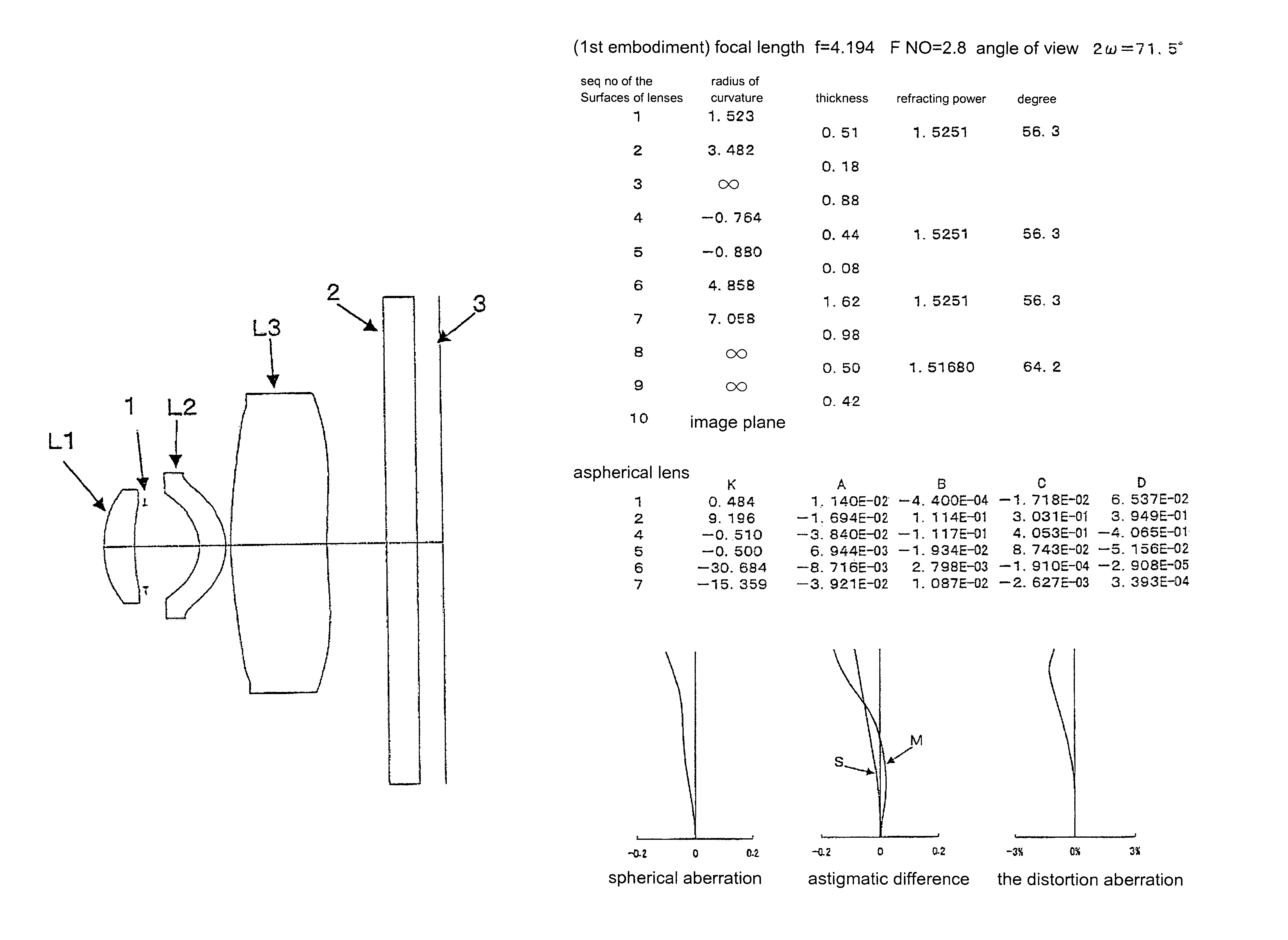
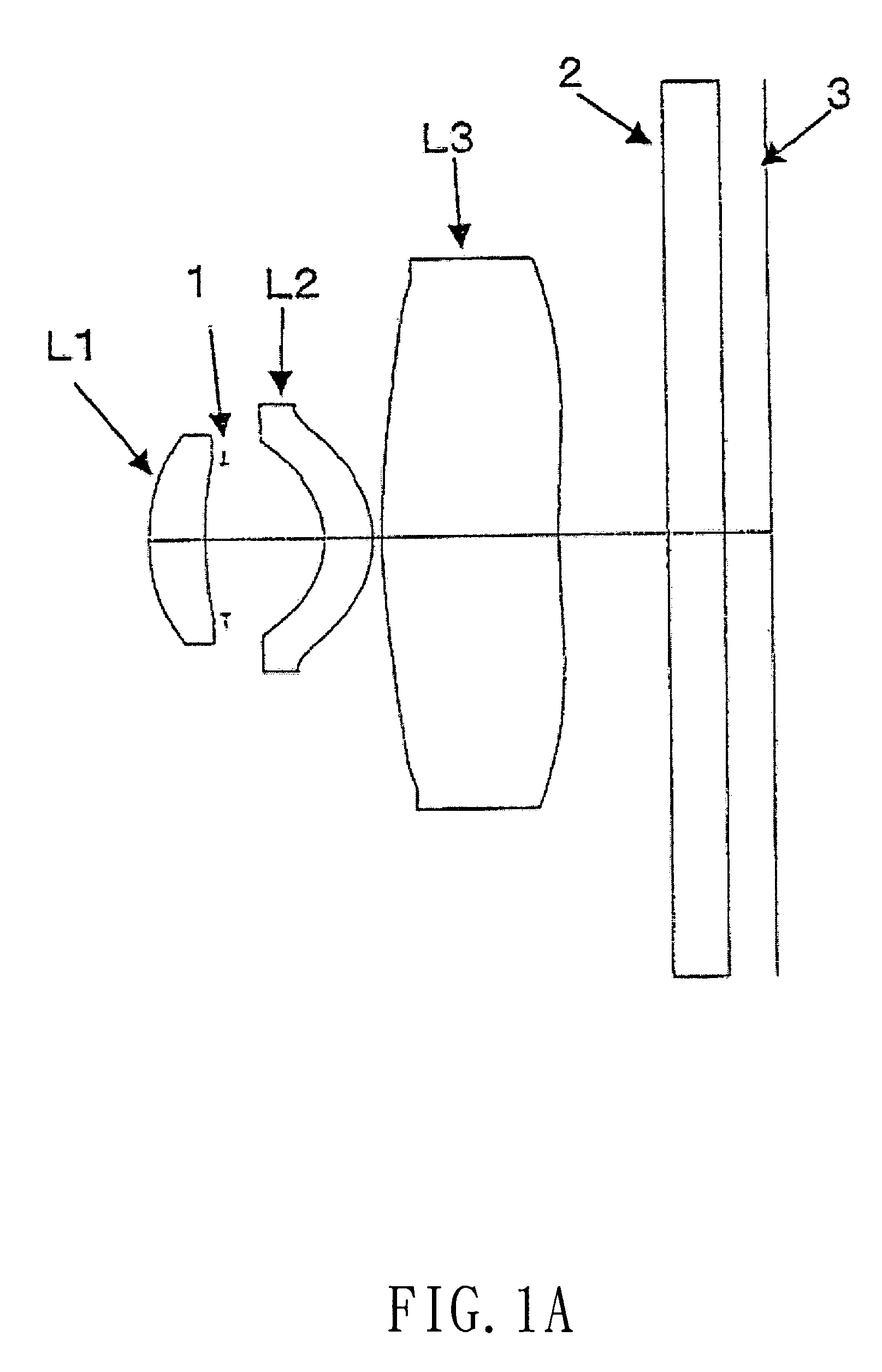
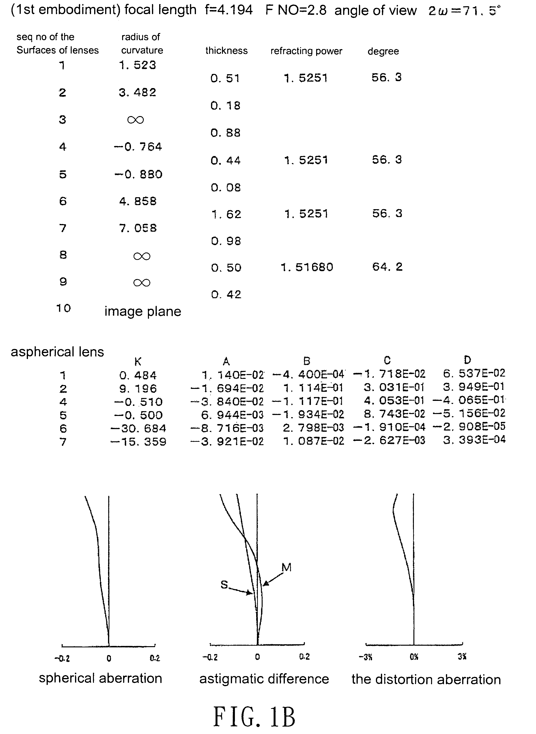
[0038]Referring to FIGS. 1–7, which show different image lens arrays in accordance with seven embodiments of the present invention, FIGS. 1a–7a show the configuration of the lens arrays, and FIGS. 1b–7b show the optical characteristic data of the lens arrays. The image-taking lens array in accordance with the present invention is particularly suitable for use as a built-in optical system for a cell phone.

[0039]The image lens array, from the object side, comprises a first lens L1, an aperture 1, a second lens L2, a third lens L3, a parallel glass 2 and an image-forming plane 3.

[0040]The first lens L1 is a positive meniscus lens with positive refractive power and has a convex surface facing the object side, the second lens L2 is positive meniscus lens with positive refractive power and has a convex surface facing the image side, and the third lens L3 is a positive meniscus lens with positive refractive power and has a convex surface facing the object side. The first and second lenses ...


PUM


Abstract

An image lens array, from object side, comprises a first lens, an aperture, a second lens and a third lens. The first lens is a positive meniscus lens with a convex surface facing the object side; the second lens is positive meniscus lens with a convex surface facing the image side; the third lens is a positive meniscus lens with a convex surface facing the object side; and the first lens, the second lens and the third lens are made of the same plastic material, a focal length of the image lens array is f, a combined focal length of the first and second lenses is f12, a relation between the f and f12 can satisfy the equation: 1.0<f12 / f<1.3.

Description

BACKGROUND OF THE INVENTION[0001]1. Field of the Invention[0002]The present invention relates to an image lens array for a small image taking device, and more particularly to an imaging lens array consisted of three lenses that are arranged at predetermined intervals.[0003]2. Description of the Prior Arts[0004]An image lens array consisted of 3 lens normally can be arranged in 8 different manners to get different refracting powers, such as: A, positive / negative / positive B, positive / positive / negative C, positive / positive / positive D, positive / negative / negative E, negative / positive / positive F, negative / positive / negative G, negative / negative / positive H, negative / negative / negative. Among the above arrangements, the back focal length of the negative refracting power type lens arrays, normally E, F, G and H, are too long to minimize the whole dimension of the lens array, and it is unsuitable for small handy image taking device. Therefore, the arrangements A–D are virtually the mainstream d...

Claims


Application Information

Patent Timeline
IPC IPC(8): G02B9/12
CPCG02B13/0035G02B9/12
Inventor NODA, SAYURI
Owner LARGAN PRECISION
Learn More