Calibration method for digital air pressure gauge

a digital air pressure gauge and calibration method technology, applied in the direction of fluid pressure measurement using pistons, instruments, measurement devices, etc., can solve the problems of unsteady airflow and the calibration of accuracy of the manufacture of pressure gauges, and achieve the effect of improving the calibration and improving the accuracy of the gaug

Inactive Publication Date: 2006-08-08
WU MIN +1
View PDF9 Cites 17 Cited by
  • Summary
  • Abstract
  • Description
  • Claims
  • Application Information

AI Technical Summary

Benefits of technology

[0008]The most difficult task in manufacturing a pressure gauge is the calibration for accuracy. The present invention is a digital tire pressure gauge and a technique directed to improve its calibration by use of a database derived from the voltage versus pressure inflation time history. During the gauge inflation the airflow is unsteady flow. The pressure varies with time, so the process of measuring a voltage versus pressure inflation time history at discrete time intervals can create the database for error compensation. A sampling of pressure input signals at discrete time intervals with very little effort can generate a series of measured voltages over the pressure range of interest. The results are then used to form a lookup table database which is stored into memory. By taking the reference pressure voltage at the same time intervals, the table has a series of measured voltages and reference pressure voltages. The voltages in each row of the lookup table have two (2) entries stored as a database to be used at later subsequent pressure measurements. At each subsequent measurement, the microprocessor reads signals from the measurement device then searches for the proper measured voltage in the lookup table database to match with that measured voltage. The microprocessor then uses the stored reference pressure voltage to replace the measured voltage for display, giving the correct values and compensating for any span, offset and linearity errors. Each digital gauge, by using the measured voltage at discrete time intervals from the voltage versus pressure inflation time history to create the lookup table database for error compensation, can have greatly improved gauge accuracy compared to what was available previously.
[0010]It is another advantage of the present invention that it provides a wireless tire pressure gauge that is easy to calibrate.

Problems solved by technology

The most difficult task in manufacturing a pressure gauge is the calibration for accuracy.
During the gauge inflation the airflow is unsteady flow.

Method used


Image

  • Calibration method for digital air pressure gauge
  • Calibration method for digital air pressure gauge
  • Calibration method for digital air pressure gauge

Examples


Embodiment Construction

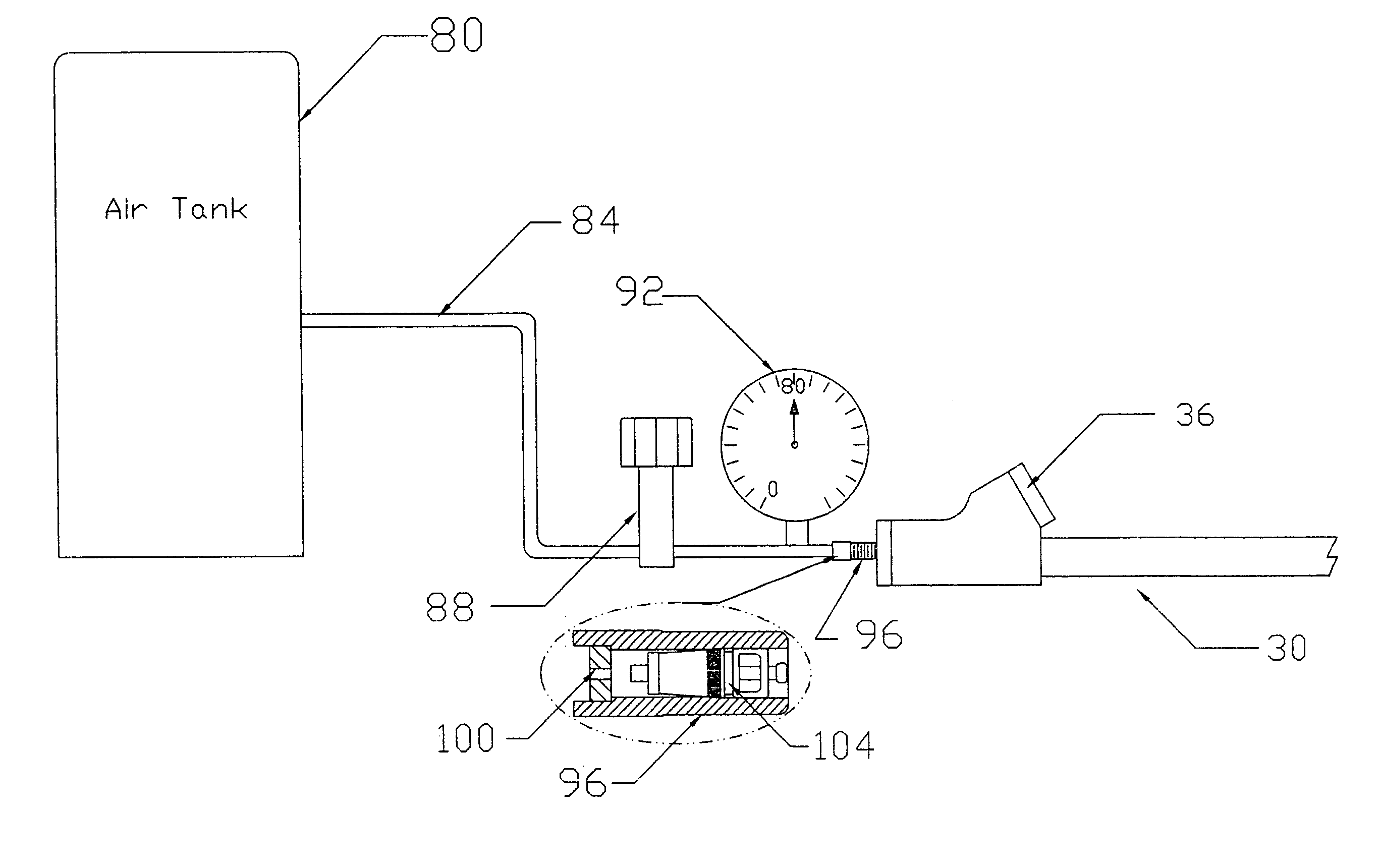
[0029]Referring to FIG. 2, the digital tire pressure gauge 30 of the present invention may have a dual-foot pressure head 36 or a single pressure head (not shown), airflow tube 38 and a cylindrical gauge tube 39. The gauge 30 includes a pressure transducer 44, including a piston 41, a spring 43, and a linear potentiometer 40 that is mechanically connected to the spring by a movable contact or wiper 48, a circular spring support 54 with an opening for the wiper 48, a printed circuit board 55 including a microprocessor 53, a liquid crystal display 57, and battery 58, all of which are disposed within the cylindrical gauge tube 39.

[0030]FIG. 3 illustrates a block diagram for the digital tire gauge indicated by reference numeral 30. The system includes a mechanical load-cell 70 (which includes the piston 41 and spring 43) to convert pressure input to displacement. The displacement is then coupled to the linear potentiometer 40 through the movable contact or wiper 48, which converts the d...


PUM

PropertyMeasurementUnit
constant pressureaaaaaaaaaa
pressureaaaaaaaaaa
air pressureaaaaaaaaaa

Abstract

The digital air pressure gauge includes an error correction lookup table database stored within a memory device within the gauge. The database includes reference air pressure values and associated measured air pressure values, where the reference air pressure values and associated measured air pressure values are determined at identical discrete time intervals as pressurized air is input into the gauge. A transducer generates an electrical signal representative of air pressure within a device such as a pneumatic tire. A microprocessor compares the electrical signal with measured air pressure values within the database and determines a closest measured air pressure value. The microprocessor then determines the associated reference air pressure value of the closest measured air pressure value. The reference air pressure value is then displayed as the accurate pressure of the pressurized air within the device. The gauge may be disposed within a tire valve cap with an RF transmitter.

Description

BACKGROUND OF THE INVENTION[0001]1. Field of the Invention[0002]The present invention relates generally to digital air pressure gauges and more particularly to calibration methods for digital tire pressure gauges.[0003]2. Description of the Prior Art[0004]A digital pressure gauge generally involves the application of a microprocessor and a pressure measurement device such as a pressure sensor or load-cell coupled with a potentiometer. The microprocessor reads data out of the pressure measurement device and stores the data. The microprocessor then carries out control functions as well as math and data storage from programming. The microprocessor automatically compensates for errors and then displays a digital signal on the liquid crystal display (LCD) or light-emitting diodes (LED).[0005]The most important thing about a digital pressure gauge is its accuracy. In pressure gauge design the input and output relationship must be predetermined, as without a defined reference relationship ...

Claims


Application Information

Patent Timeline
Patent Type & Authority Patents(United States)
IPC IPC(8): G01L27/02G01L17/00G01L19/14G01L7/16G01L27/00G01M3/02
CPCG01L17/00G01L27/002G01L27/02
Inventor WU, MINLIN, SHEN-CHI
Owner WU MIN
Why Eureka
Try Eureka