Sequential punch press with complementary sliding plates

a technology of sliding plate and punch press, which is applied in the field of sequential punch press, can solve the problems of inconvenient and time-consuming, high cost of laser machining, and low use rate, and achieve the effect of preparing and efficiently machine long workpieces

Inactive Publication Date: 2006-08-08
HON HAI PRECISION IND CO LTD
View PDF27 Cites 12 Cited by
  • Summary
  • Abstract
  • Description
  • Claims
  • Application Information

AI Technical Summary

Benefits of technology

[0006]Accordingly, an object of the present invention is to provide a sequential punch press which can readily and efficiently machine long workpieces.

Problems solved by technology

However, laser machining is costly and is therefore not widely used.
However, it is problematic when the workpiece is required to be machined at irregular intervals.
All these requirements are inconvenient and time-consuming.

Method used


Image

  • Sequential punch press with complementary sliding plates
  • Sequential punch press with complementary sliding plates
  • Sequential punch press with complementary sliding plates

Examples


Embodiment Construction

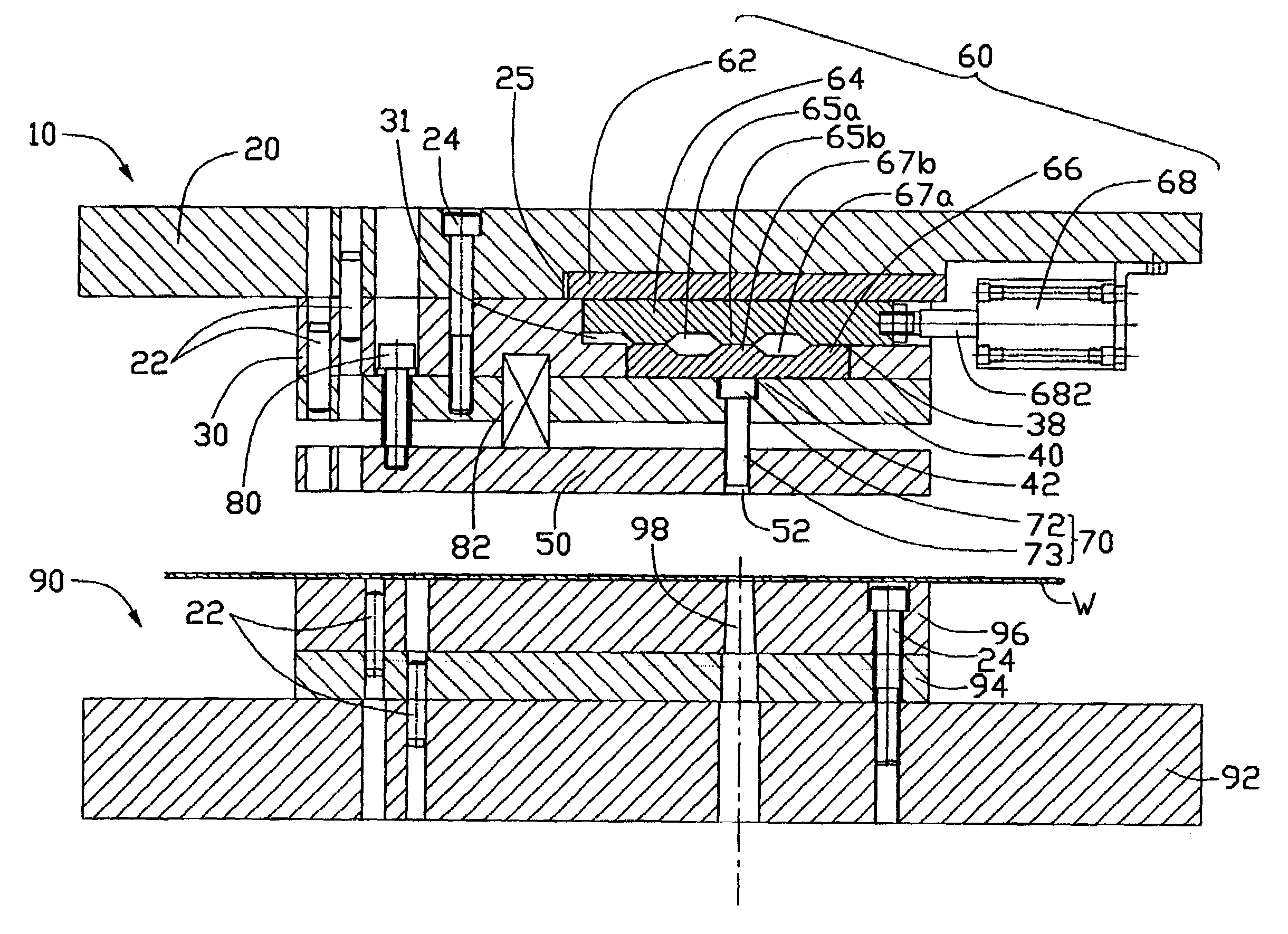
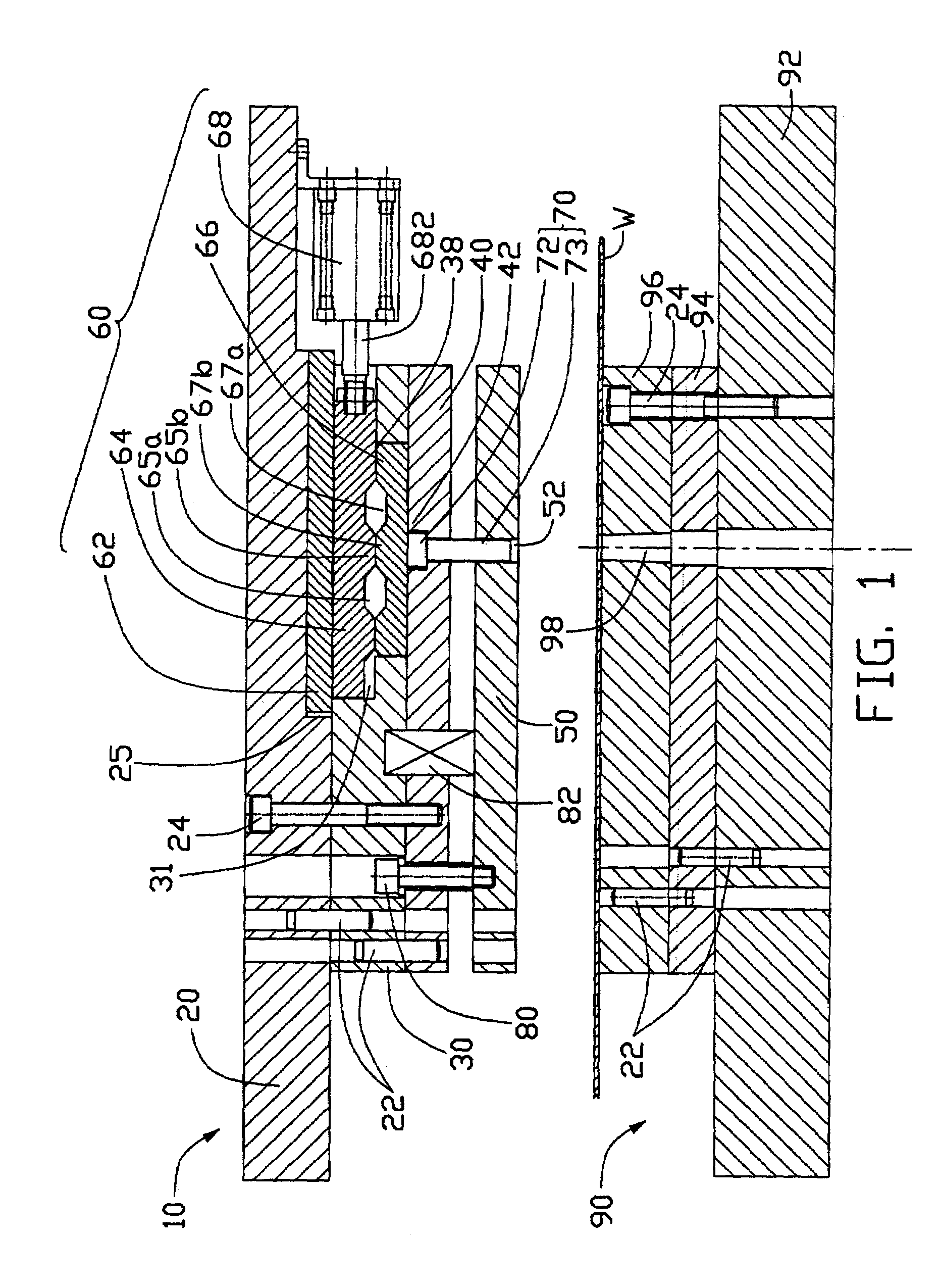
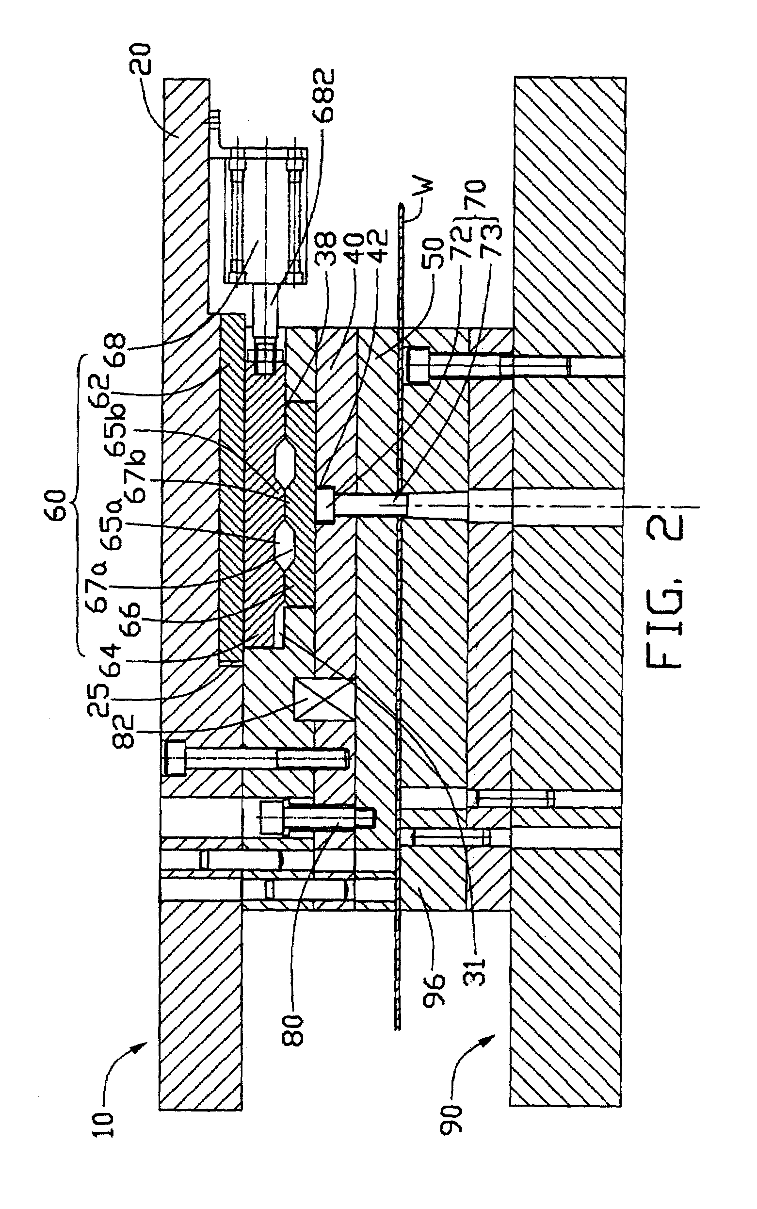
[0012]Referring to FIG. 1, a sequential punch press for sequentially punching a workpiece W in accordance with the present invention comprises an upper die 10 and a lower die 90. The upper die 10 sequentially comprises, from top to bottom, a punch set 20, a punch pad 30, a punch holder 40 and a stripper 50. The punch set 20, punch pad 30, and punch holder 40 are fixedly secured together by pins 22 and bolts 24. The stripper 50 is movably secured under the punch holder 40 by a fastener 80 that movably extends through the punch holder 40 to engage with the stripper 50. In the preferred embodiment, the fastener 80 is a screw 80. A spring 82 extends through the punch holder 40. One end of the spring 82 is received in the punch pad 30, and an opposite end of the spring 82 is fixed on the stripper 50. The punch holder 40 defines a first cutout 42 in a top wall thereof. The stripper 50 defines a through hole 52 therein. A punch 70 is vertically and movably secured in the punch holder 40. T...


PUM

PropertyMeasurementUnit
distanceaaaaaaaaaa
lengthaaaaaaaaaa
timeaaaaaaaaaa

Abstract

A sequential punch press includes an upper die (10), a lower die (90), and an adjusting device (60) in the upper die. The upper die sequentially includes a punch set (20), a punch pad (30), a punch holder (40), and a stripper (50). A punch (70) is vertically and movably secured in the punch holder and received in the stripper. The adjusting device includes first and second sliding plates (64, 66) respectively having protrusions (65b, 67b), a piston cylinder (68) having a piston rod (682) fixedly connected with the first sliding plate, and a programmable controller for causing the piston rod to slidingly move the first sliding plate. When the first protrusions opposingly abut the second protrusions, the punch can extend beyond the stripper to punch a workpiece. When the first protrusions do not opposingly abut the second protrusions, the punch cannot extend beyond the stripper to punch the workpiece.

Description

BACKGROUND OF THE INVENTION[0001]1. Field of the Invention[0002]The present invention relates to sequential punch presses, and particularly to a sequential punch press with a punch which can selectively punch a workpiece.[0003]2. Description of Related Art[0004]Various electronic devices are ubiquitous in modem society. For example, computer servers and routers pervade the business world. Enclosures of such electronic devices are usually formed by processes including punching.[0005]Conventional means for forming enclosures from a workpiece comprise, for example, laser machining and conventional sequential punch machining. However, laser machining is costly and is therefore not widely used. Conventional sequential punch machining involves a series of stages of machining the workpiece. The workpiece is sequentially moved a same fixed distance at each stage of machining. This provides convenient machining when the workpiece is required to be machined at regular fixed intervals. However...

Claims


Application Information

Patent Timeline
Patent Type & Authority Patents(United States)
IPC IPC(8): B26F1/04B26F1/14B21D28/24
CPCB26F1/04B21D28/246Y10T83/9423Y10T83/8748Y10T83/04Y10T83/943Y10T83/8867Y10T83/8727
Inventor YANG, CHIA HSIANGCHIANG, CHUN-HSIENWU, ZAI XINGTANG, LIU SHENGYANG, YOU CAILIU, KE
Owner HON HAI PRECISION IND CO LTD
Why Eureka
Try Eureka