Collapsible nut

a technology of cage nuts and nut nuts, which is applied in the direction of threaded fasteners, screws, fastening means, etc., can solve the problems of high manufacturing cost of cage nuts, buzzing, squeak rattle (“bsr”) issues with customers, and the like, so as to reduce the possibility of the nut sticking to the cage

Inactive Publication Date: 2006-08-08
ACUMENT INTPROP LLC
View PDF87 Cites 15 Cited by
  • Summary
  • Abstract
  • Description
  • Claims
  • Application Information

AI Technical Summary

Benefits of technology

[0007]A primary object of an embodiment of the present invention is to provide a cage nut assembly which

Problems solved by technology

Problems have arisen in conjunction with prior art cage nut assemblies.
One problem occurs after the cages of the cage nut assemblies are welded to a mating surface, such as an automobile frame.
These flattenable projections either on the cage or the nut, or the addition of a third part with the flattenable projections thereon, provide high manufacturing costs to the cage nut assembly.
The addition of the plastic rings to the cage nut assembly

Method used


Image

  • Collapsible nut
  • Collapsible nut
  • Collapsible nut

Examples


first embodiment

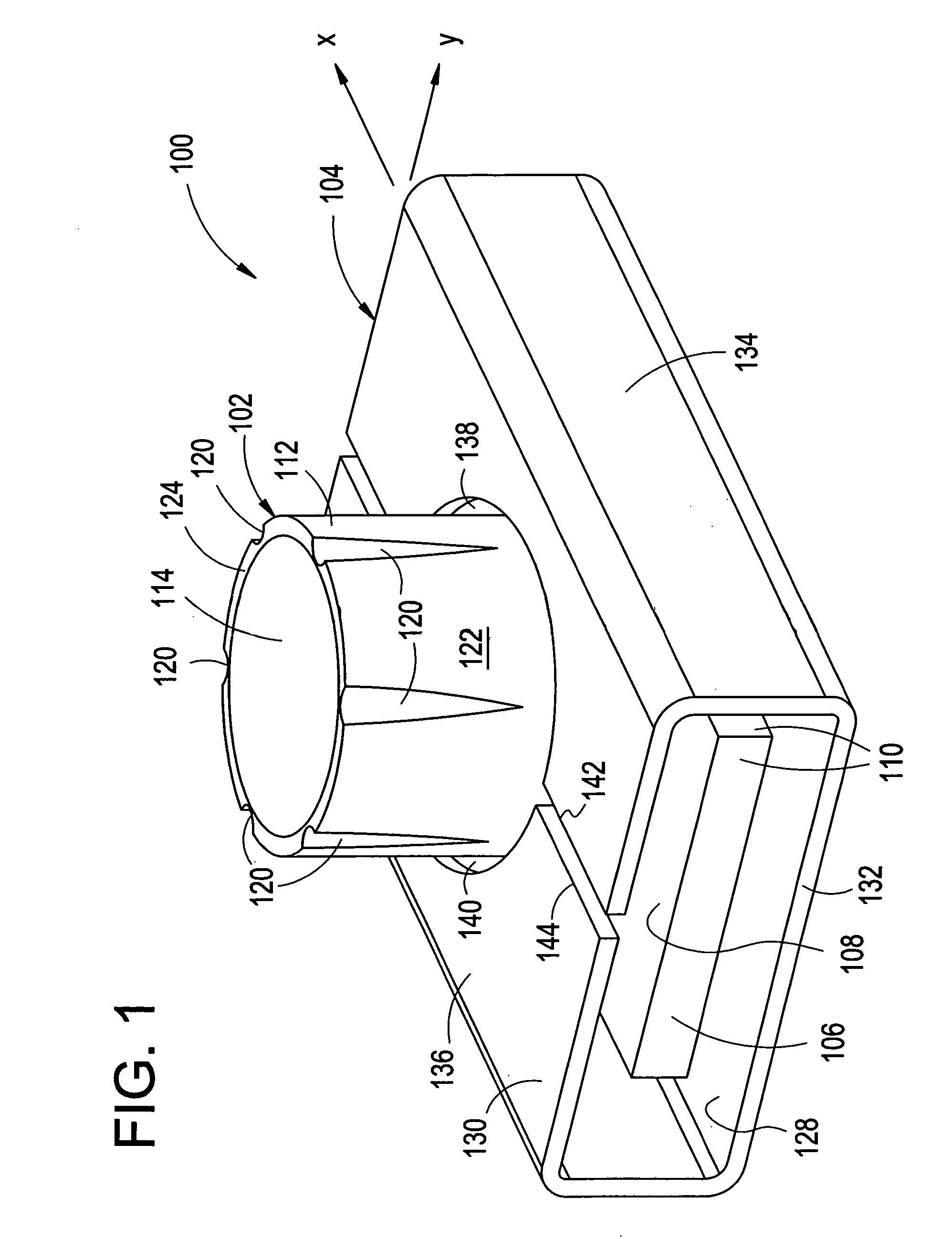
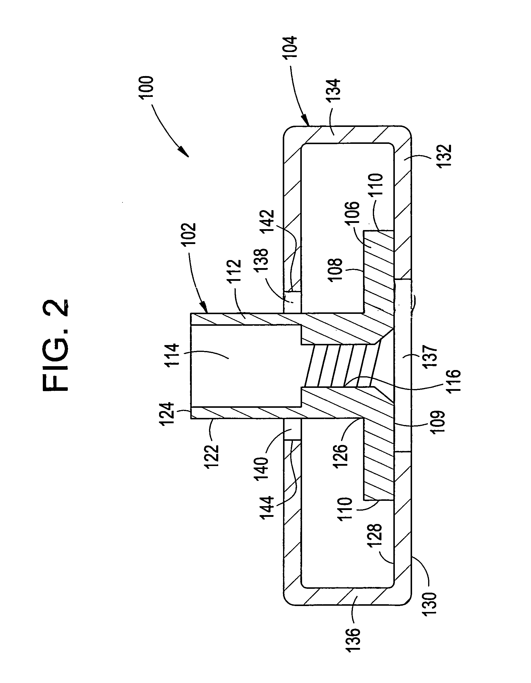
[0047]Attention is directed to a cage nut assembly 100 which is in accordance with the present invention, and which is best illustrated in FIGS. 1–6. The cage nut assembly 100 includes a nut 102 and a cage 104.

[0048]The nut 102 is best illustrated in FIGS. 1 and 2. The nut 102 includes a rectangular plate or base portion 106 having a generally planar upper surface 108, a generally planar lower surface 109, and sidewalls 110 which connect the upper surface 108 to the lower surface 109. The nut 102 also includes a cylindrical member 112 which extends outwardly from the upper surface 108 of the nut 102. The cylindrical member 112 is preferably in the form of a right circular cylinder. An aperture 114 extends through the nut 102 from the plate 106 into the cylindrical member 112. The aperture 114 maybe closed at the lower surface 109 of the plate 106 or it may, preferably, extend all the way through the plate 106. The aperture 114 defines an aperture wall 116 which is preferably threade...

second embodiment

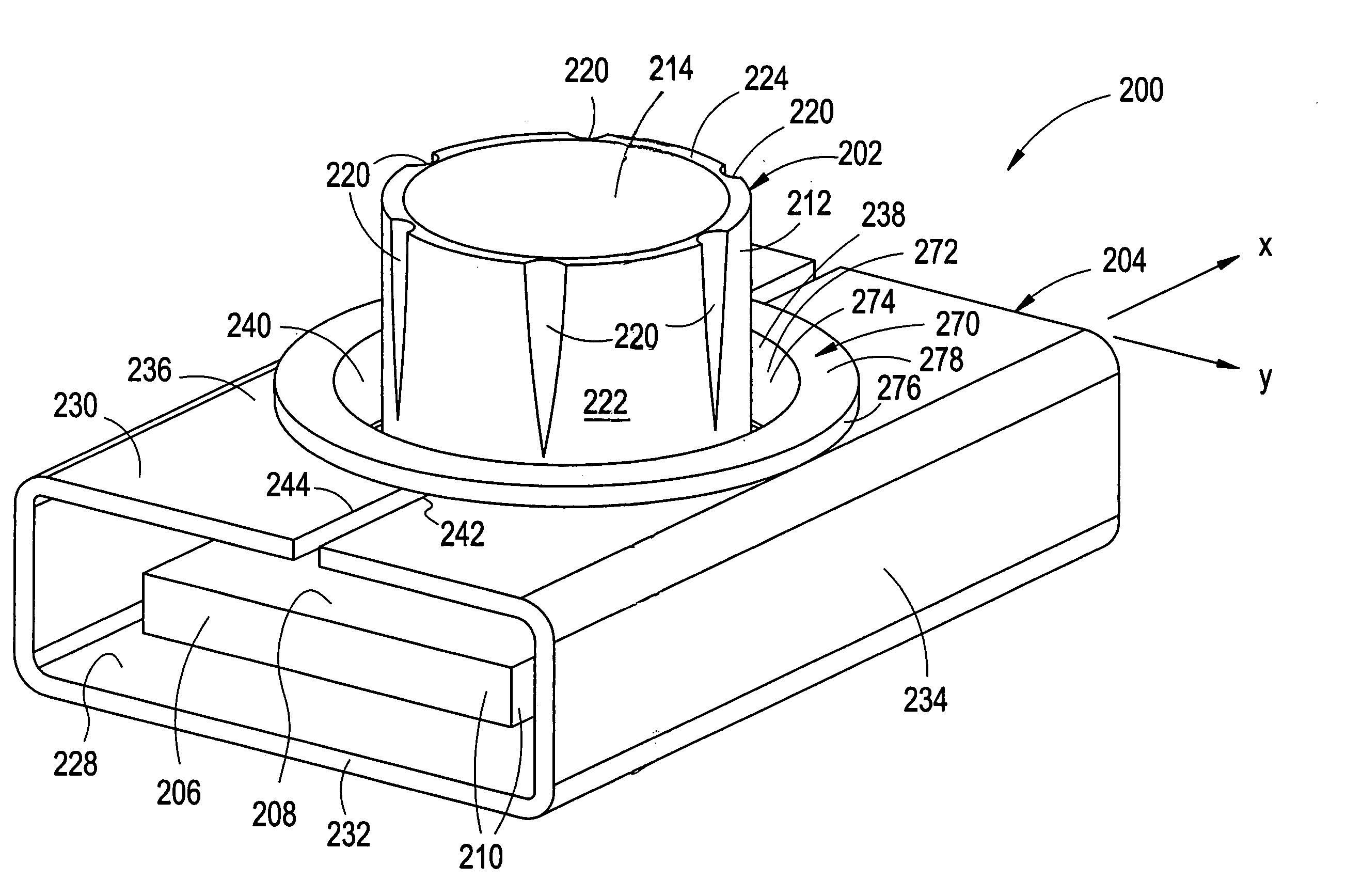
[0061]Attention is directed to a cage nut assembly 200 which is in accordance with the present invention, and which is best illustrated in FIGS. 7–12. The cage nut assembly 200 includes a nut 202, a cage 204 and a bushing 270.

[0062]The nut 202 is best illustrated in FIGS. 7 and 8. The nut 202 includes a rectangular plate or base portion 206 having a generally planar upper surface 208, a generally planar lower surface 209, and sidewalls 210 which connect the upper surface 208 to the lower surface 209. The nut 202 also includes a cylindrical member 212 which extends outwardly from the upper surface 208 of the nut 202. The cylindrical member 212 is preferably in the form of a right circular cylinder. An aperture 214 extends through the nut 202 from the plate 206 into the cylindrical member 212. The aperture 214 maybe closed at the lower surface 209 of the plate 206 or it may, preferably, extend all the way through the plate 206. The aperture 214 defines an aperture wall 216 which is pr...

third embodiment

[0081]Attention is directed to a cage nut assembly 300 which is in accordance with the present invention, and which is best illustrated in FIGS. 13–18. The cage nut assembly 300 includes a nut 302 and a cage 304.

[0082]The nut 302 is best illustrated in FIGS. 13 and 14. The nut 302 includes a rectangular plate or base portion 306 having a generally planar upper surface 308, a generally planar lower surface 309, and sidewalls 310 which connect the upper surface 308 to the lower surface 309. The nut 302 also includes a cylindrical member 312 which extends outwardly from the upper surface 308 of the nut 302. The cylindrical member 312 is preferably in the form of a right circular cylinder. An aperture 314 extends through the nut 302 from the plate 306 into the cylindrical member 312. The aperture 314 may be closed at the lower surface 309 of the plate 306 or it may, preferably, extend all the way through the plate 306. The aperture 314 defines an aperture wall 316 which is preferably th...


PUM


Abstract

A cage nut assembly includes a nut having a cylindrical portion extending from a plate portion. The nut is encaged in a cage such that the cylindrical portion extends through an aperture in the cage. The cylindrical portion of the nut is collapsible such that the nut collapses and provides a plurality of flanges upon an application of force. The flanges are folded or curved/mushroomed such that the plate portion of the nut is suspended within the cage so that the nut will not, or will minimally, stick to the cage or workpiece when coated with e-coat or ELPO. Upon torqueing a fastener into place, the flanges are bent up to allow the plate portion to interface with the cage or a workpiece to provide a solid joint.

Description

BACKGROUND OF THE INVENTION[0001]The present invention relates to a cage nut assembly, a nut used in the cage nut assembly, and a method of forming the cage nut assembly.[0002]Cage nut assemblies are well known in the art and provide a useful function in that they are able to hold a threaded nut at locations in a frame that are difficult or in some cases impossible to reach with a tool. Cage nut assemblies are used in vehicles for seat attachments, radiator attachments, chassis to drive train attachments, and for any other nut application that requires the nut to have an “X” and “Y” axis adjustability to accommodate tolerance variations and enable engagement thereof by a male threaded fastener.[0003]Problems have arisen in conjunction with prior art cage nut assemblies. One problem occurs after the cages of the cage nut assemblies are welded to a mating surface, such as an automobile frame. After the cages are welded to the automobile frame, the frames are sent through an e-coat or ...

Claims


Application Information

Patent Timeline
IPC IPC(8): F16B39/284F16B39/28F16B37/04F16B37/06
CPCF16B37/065F16B37/044
Inventor CLINCH, JAMES PATRICKPURDY, PAUL DOUGLASTURNMIRE, WILLIAM ROBERT
Owner ACUMENT INTPROP LLC
Why Eureka
Try Eureka