
Interlocking member for an electrical connector

a technology of interlocking member and electrical connector, which is applied in the direction of coupling device details, coupling device connection, electric discharge lamp, etc., can solve the problems of plugging connectors of the prior art, and achieve the effect of reliable interconnection

Inactive Publication Date: 2006-08-08
HON HAI PRECISION IND CO LTD
View PDF11 Cites 28 Cited by
  • Summary
  • Abstract
  • Description
  • Claims
  • Application Information

AI Technical Summary

Benefits of technology

[0008]Therefore, a main object of the present invention is to provide an improved electrical connector having an insulative casing and interlocking members assembled with the insulative casing, wherein the insulative casing provides extension to enclose the interlocking members therein so as to realize reliable interconnection between the electrical connector and a mating connector.

Problems solved by technology

However, the plug connectors of the prior arts involve a common problem as the latch hook of the flexible latch arms and the claws of the fastening mechanisms are exposed outside and have no any protections.
This drawback will be most prominent in case of encountering impact from unexpected exterior sources so as to unfortunately influent stabilization of the electrically interconnection between the plug connector and the receptacle connector / plug socket.

Method used


Image

  • Interlocking member for an electrical connector
  • Interlocking member for an electrical connector
  • Interlocking member for an electrical connector

Examples


Embodiment Construction

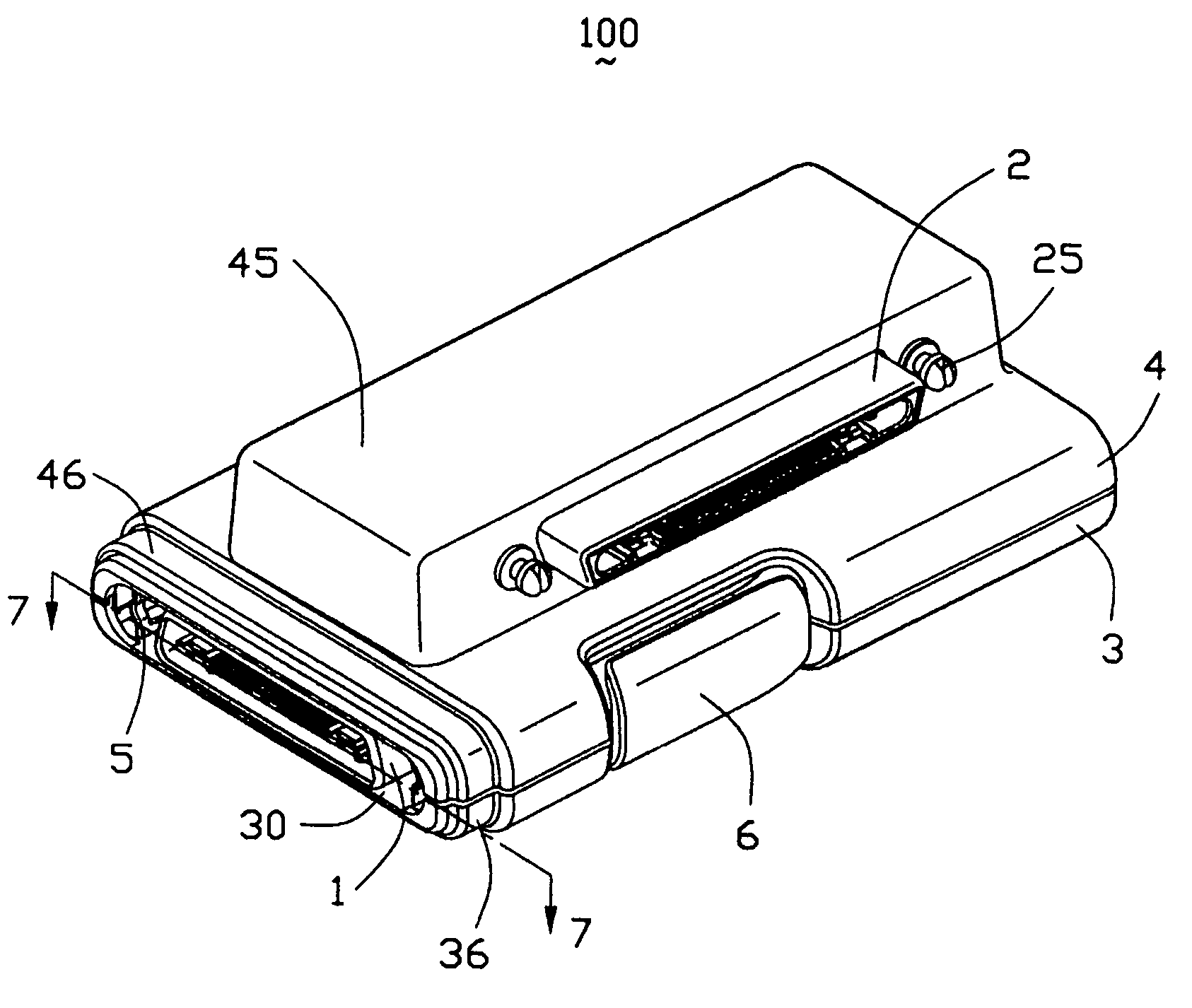
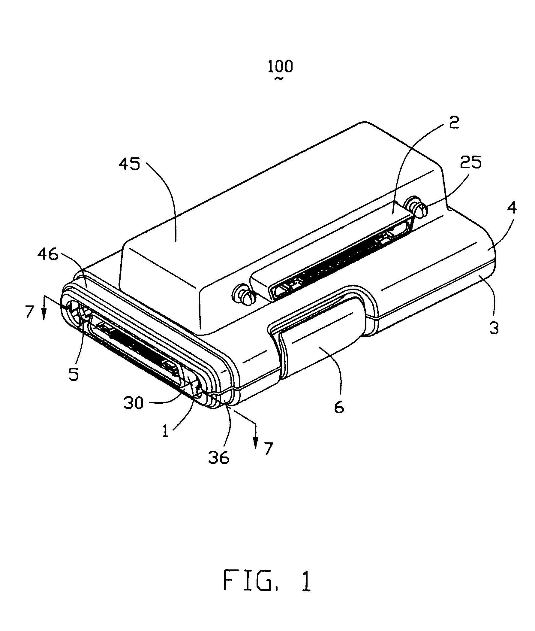
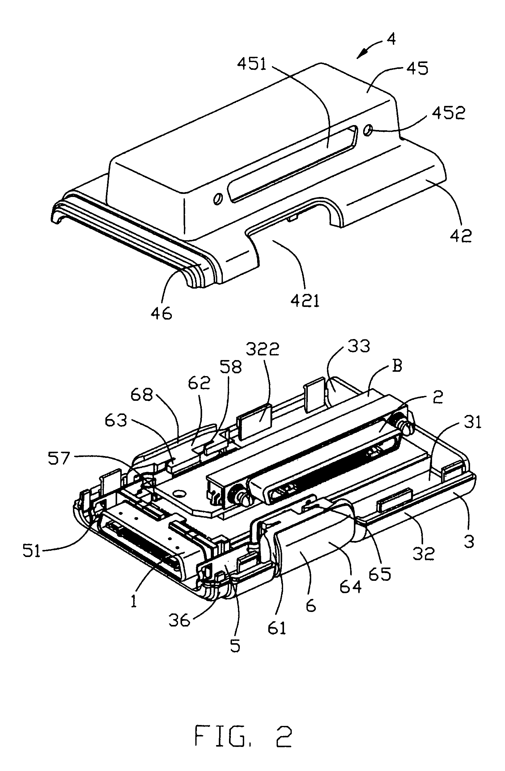
[0019]Referring to the drawings in greater detail, and first to FIGS. 1 and 4, an electrical connector 100 according to the present invention comprises an insulative casing, a first connector unit 1, a second connector unit 2, a printed circuit board module and a pair of interlocking members. In the preferred embodiment, the electrical connector 100 is an electrical adapter adapted for realizing electrically connection between a Notebook and a docking station. Furthermore, the insulative casing is a rectangular contour and includes a lower half 3 and an upper half 4 engaged with each other which together define a receiving space (not labeled) therebetween. The receiving space is provided with a first opening 30 occupied by the first connector unit 1 and a second opening 451 occupied by the second connector unit 2. The printed circuit board module includes a printed circuit board A electrically connected with the first connector unit 1, a printed circuit board B electrically connecte...


PUM


Abstract

An electrical connector (100) includes a module (1) having a mating portion (115) embedded with a plurality of terminals (13), an interlocking member having a press member (6) and an elongated latch member (5) assembled with the press member, and an insulative casing (3, 4) forming an extension (36, 46) to enclose the mating portion of the module and the latch member of the interlocking member.

Description

CROSS-REFERENCE TO RELATED APPLICATION[0001]This application is related to co-pending U.S. patent application Ser. No. 11 / 028,104 entitled “ELECTRICAL ADAPTER”, invented by the same inventor and assigned to the common assignee as the present invention.BACKGROUND OF THE INVENTION[0002]1. Field of the Invention[0003]The present invention relates to an electrical connector, and more particularly to an interlocking member for an electrical connector, providing reliable mating / unmating interface for securing the electrical connector to a mating electrical device.[0004]2. Description of the Prior Art[0005]Complementary electrical connectors typically include dielectric housings respectively receiving a plurality of terminals or contacts which, when the connectors are mated, establish an electrical interconnection therebetween. The complementary connectors may be male and female connectors or plug and socket connectors for electrically connecting the terminals or contacts received therein....

Claims


Application Information

Patent Timeline
Patent Type & Authority Patents(United States)
IPC IPC(8): H01R13/627H01R9/22H01R13/639H01R31/06
CPCH01R13/6395H01R31/06H01R2201/06
Inventor YIN, HAO MAICHENG, WEI YA
Owner HON HAI PRECISION IND CO LTD
Learn More