Electrical connector

a technology of electrical connectors and connectors, applied in the direction of coupling devices, two-part coupling devices, electrical apparatus, etc., can solve the problems of impedance mismatch in high-speed signal transmission, and achieve the effect of minimizing the capacitance between the pair of connection lands

Inactive Publication Date: 2006-08-08
HIROSE ELECTRIC GROUP
View PDF6 Cites 5 Cited by
  • Summary
  • Abstract
  • Description
  • Claims
  • Application Information

AI Technical Summary

Benefits of technology

[0007]Accordingly, it is an object of the invention to provide an electrical connector and a circuit board capable of minimizing the capacitance produced between the corresponding connection lands of the circuit board.
[0009]Since the corresponding connection lands are offset in the second direction, the overlap area of the corresponding connection lands is reduced, thereby minimizing the capacitance produced between the corresponding connection lands.
[0010]The contact sections of the terminal may be offset in the first direction so that the second board is plugged at two stages, resulting in the reduced plugging force. It is preferred that the contact sections of terminals are staggered in the first direction, thereby preventing the second board from tilting in the third direction. The second board may be an arranging board of a second connector or an interconnection board having connection lands on another edge area to be connected to a second connector.
[0013]As has been described above, according to the invention, the connection lands provided on both sides of a second board and short circuited in corresponding pairs are offset in the second direction so that the capacitance between the pairs of connection lands is minimized, making a good high-speed signal transmission path between the terminal and the connection lands.

Problems solved by technology

However, the capacitance of the connection sections is so large as to cause impedance mismatch in high-speed signal transmissions.

Method used


Image

  • Electrical connector
  • Electrical connector
  • Electrical connector

Examples


Embodiment Construction

[0021]An embodiment of the invention will now be described with reference to FIGS. 1–6.

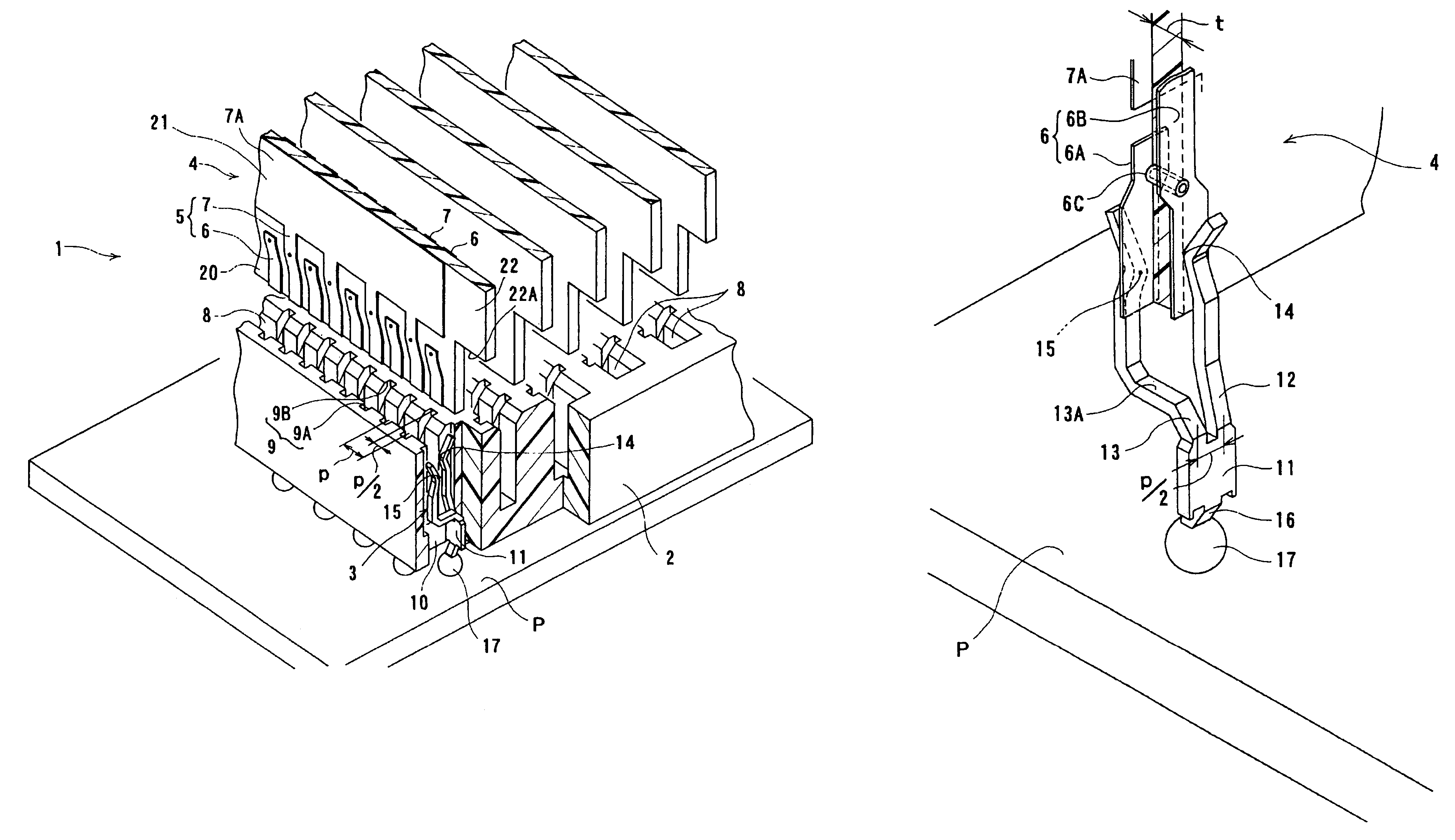
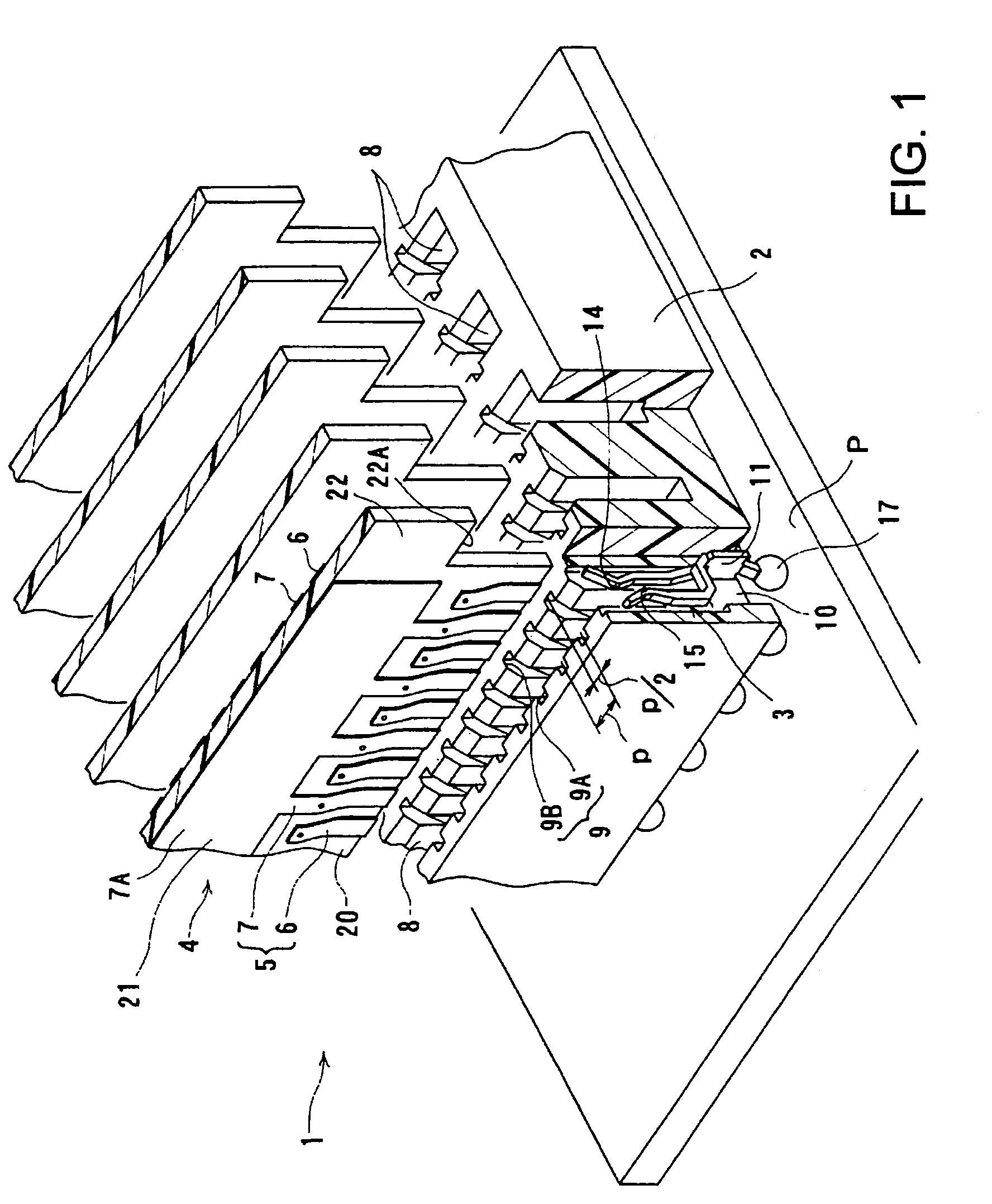
[0022]In FIG. 1, a connector 1 is attached to a printed circuit (PC) board P for example. The circuit section to which a terminal of the connector 1 is to be connected is omitted from the drawing. The connector 1 includes a housing 2 made of an insulative material and a plurality of terminals 3 that are made by stamping and bending a sheet of metal and arranged in the housing 2.

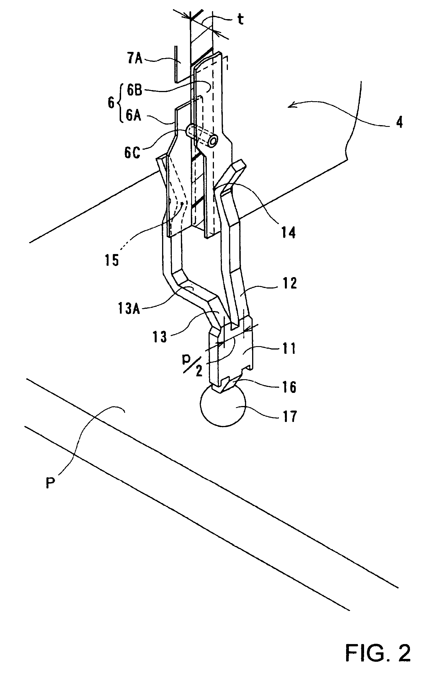
[0023]The housing 2 has a rectangular shape and a plurality of rows of receiving recesses 8 extending downward from the top face for receiving in the plugging direction a connection section 5 including signal connection lands 6 and ground connection lands 7 of a daughter board 4. A pair of terminal grooves 9 (9A, 9B) for receiving a pair of opposed contact sections of each terminal 3 are provided in opposed walls of the receiving recess 8. The opposed terminal grooves 9A and 9B are offset by p / 2 in the terminal arranging di...


PUM


Abstract

An electrical connector includes an insulative housing (2) attachable to a first board and having a receiving recess (8) for receiving a second board in a first direction; and a plurality of terminals (3) arranged in the receiving recess in a second direction perpendicular to the first direction. Each terminal (3) has a pair of contact sections (14, 15) to be brought into spring contact with a pair of connection lands (5) provided on front and back edge sections (20) on front and back surfaces of a second board. The pair of connection lands (5) on the front and back edge sections are short-circuited and offset in the second direction. The pair of contact sections are offset in the second direction.

Description

BACKGROUND OF THE INVENTION[0001]1. Field of the Invention[0002]The present invention relates to an electrical connector having terminals with contact sections in spring contact with the connection sections provided on front and back sides of a board and such a board.[0003]2. Description of the Related Art[0004]JP 2001-143786 discloses two connectors connected by an interconnection board. The interconnection board has a plurality of connection lands arranged on opposite edges of front and back sides thereof. The connection lands in corresponding pairs on the front and back sides are short-circuited with conductive through-holes.[0005]The connector has a plurality of terminals each with a pair of contact sections to be brought into spring contact with the connection lands provided on the front and back sides of the interconnection board.[0006]However, the capacitance of the connection sections is so large as to cause impedance mismatch in high-speed signal transmissions. The area of ...

Claims


Application Information

Patent Timeline
Patent Type & Authority Patents(United States)
IPC IPC(8): H01R31/06H01R4/02H01R12/00
CPCH01R4/028H01R23/688H01R12/57H01R13/6585
Inventor TAKADA, TOSHIYUKI
Owner HIROSE ELECTRIC GROUP
Why Eureka
Try Eureka