
Partial printing of a substrate with edge sealed printed portions

a printing portion and substrate technology, applied in the direction of printing process, duplicating/marking method, decorative arts, etc., can solve the problem that re37,186 cannot be reliably produced without conventional printing methods

Inactive Publication Date: 2006-08-08
CONTRA VISION
View PDF20 Cites 14 Cited by
  • Summary
  • Abstract
  • Description
  • Claims
  • Application Information

AI Technical Summary

Problems solved by technology

However, these methods typically involve the use of special inks and additional production stages compared to the simple deposition of layers of ink or other marking material.
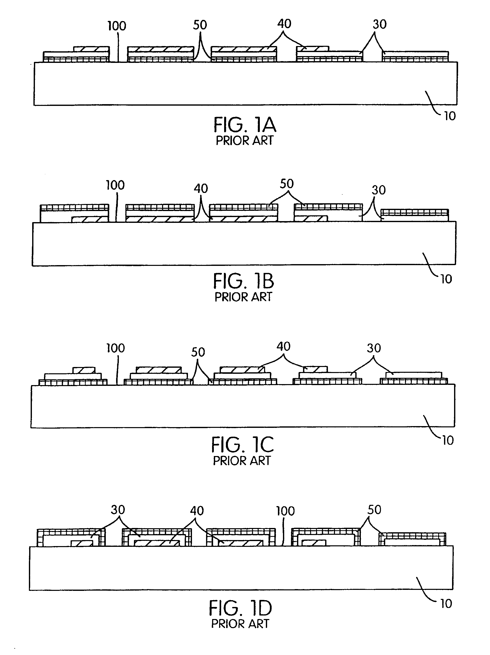
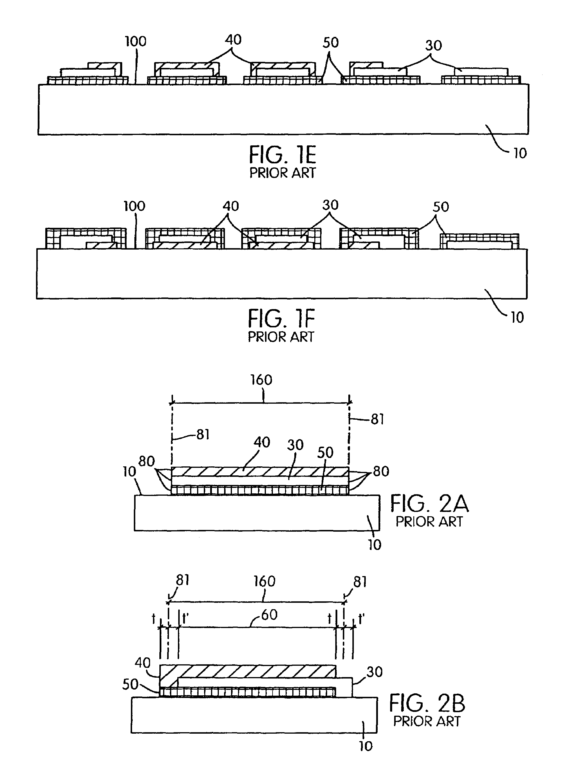
U.S. Pat. No. 6,210,776 discloses why conventional printing processes all suffer inexact registration, owing to:—i) printing machine error or “tolerance” in delivering ink or other marking material,ii) the dimensional instability of a liquid ink or other marking material in liquid state on a substrate,iii) the dimensional instability of a substrate through temperature and humidity changes between printing “passes” (printing of individual layers), andiv) the error or “tolerance” in delivery of a substrate into the printing position.
Panels according to US RE37,186 cannot be reliably produced with conventional printing methods without special measures to overcome the otherwise inevitable color variance from that desired, both over the area of a single panel and between panels within a production run.

Method used


Image

  • Partial printing of a substrate with edge sealed printed portions
  • Partial printing of a substrate with edge sealed printed portions
  • Partial printing of a substrate with edge sealed printed portions

Examples


Embodiment Construction

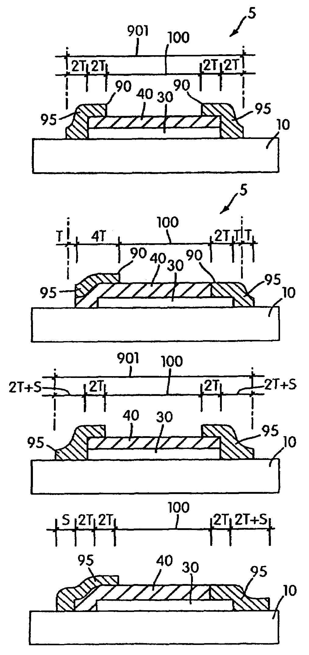
[0022]According to the present invention a panel comprises a substantially imperforate substrate and a print pattern disposed on said substrate, said print pattern being disposed on only part of said substrate and comprising at least three layers including a first layer, a second layer, and a control layer, said first layer, said second layer, and said control layer being configured and disposed such that a cross-section taken through said panel comprises two outer edges of said substrate and alternate printed portions of said substrate and unprinted portions of said substrate, each said printed portion having two outer edges, and wherein within said cross-section of said panel each of a plurality of said printed portions being constructed and arranged such that they each include a part of said first layer and a part of said second layer and a part of said control layer, said plurality of said printed portions each including two outer edges of said part of said first layer and two o...


PUM

PropertyMeasurementUnit
widthaaaaaaaaaa
widthaaaaaaaaaa
widthaaaaaaaaaa

Abstract

This invention relates to the partial printing of a substrate with a plurality of layers to form a partially printed panel. Within each printed portion, at least one layer is applied to the substrate with inexact registration in relation to a second layer. A “control layer” comprising “edge sealing strips” is printed so that, within each printed portion, each edge of the at least two layers with inexact registration is located within the edges of an overlapping edge sealing strip. The edge sealing strips may provide a visual seal or mask at the edges of printed portions, for example to enable the each printed portion to have the desired color rendering within a one-way vision control panel. The invention can comprise the physical sealing of printed portions containing gaseous or liquid fluids or particles in suspension, such as fragrances, medication, environmentally reactive materials or security printing features.

Description

[0001]This application is the National Phase of International Application PCT / IB02 / 01549 filed Jan. 18, 2002 which designated the U.S. and that International Application was published in English under PCT Article 21(2) on Sep. 12, 2002 as International Publication No. WO 02 / 070269 A2. PCT / IB02 / 01549 is a continuation-part and claims priority to U.S. patent application Ser. No. 09 / 764,276, filed Jan. 19, 2001, now issued as U.S. Pat. No. 6,506,475. The entire contents of these applications are incorporated herein by reference.[0002]The present invention is a continuation-in-part of U.S. patent application Ser. No. 09 / 764,276 filed Jan. 19, 2001 and herein incorporated by reference.BACKGROUND TO THE INVENTION[0003]This invention relates to the partial printing of a substrate with a plurality of layers to form a partially printed panel. Within each printed portion, at least one layer is applied to the substrate with inexact registration in relation to a second layer. A “control layer” ...

Claims


Application Information

Patent Timeline
Patent Type & Authority Patents(United States)
IPC IPC(8): B32B23/02B41M1/18B41M3/00B44C3/02B44C5/04B44F3/00
CPCB41M1/18B41M3/008B44C3/02B44F3/00B44C5/0446B41M3/006Y10T428/2486Y10T428/24793Y10T428/24802Y10T428/24736
Inventor HILL, ROLAND G
Owner CONTRA VISION
Learn More