Flow field geometries for improved water management

a flow field and geometrie technology, applied in the field of fuel cells, can solve the problems of water being impeded from flowing outward from the mea, often referred to as flood, and hindering the operation of fuel cells

Active Publication Date: 2006-08-08
GM GLOBAL TECH OPERATIONS LLC
View PDF5 Cites 27 Cited by
  • Summary
  • Abstract
  • Description
  • Claims
  • Application Information

AI Technical Summary

Problems solved by technology

A drawback of fuel cells, however, is the phenomenon of water being impeded from flowing outward from the MEA, often referred to as “flooding”.
Flooding can hinder a fuel cell's operation at low current density when the air flow through the cathode flow field plate is not sufficient to drive the water removal process.

Method used


Image

  • Flow field geometries for improved water management
  • Flow field geometries for improved water management
  • Flow field geometries for improved water management

Examples


Embodiment Construction

[0020]The following description of the preferred embodiments is merely exemplary in nature and is in no way intended to limit the invention, its application, or uses.

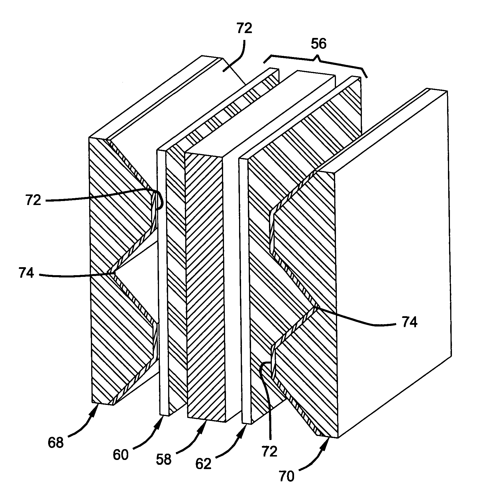
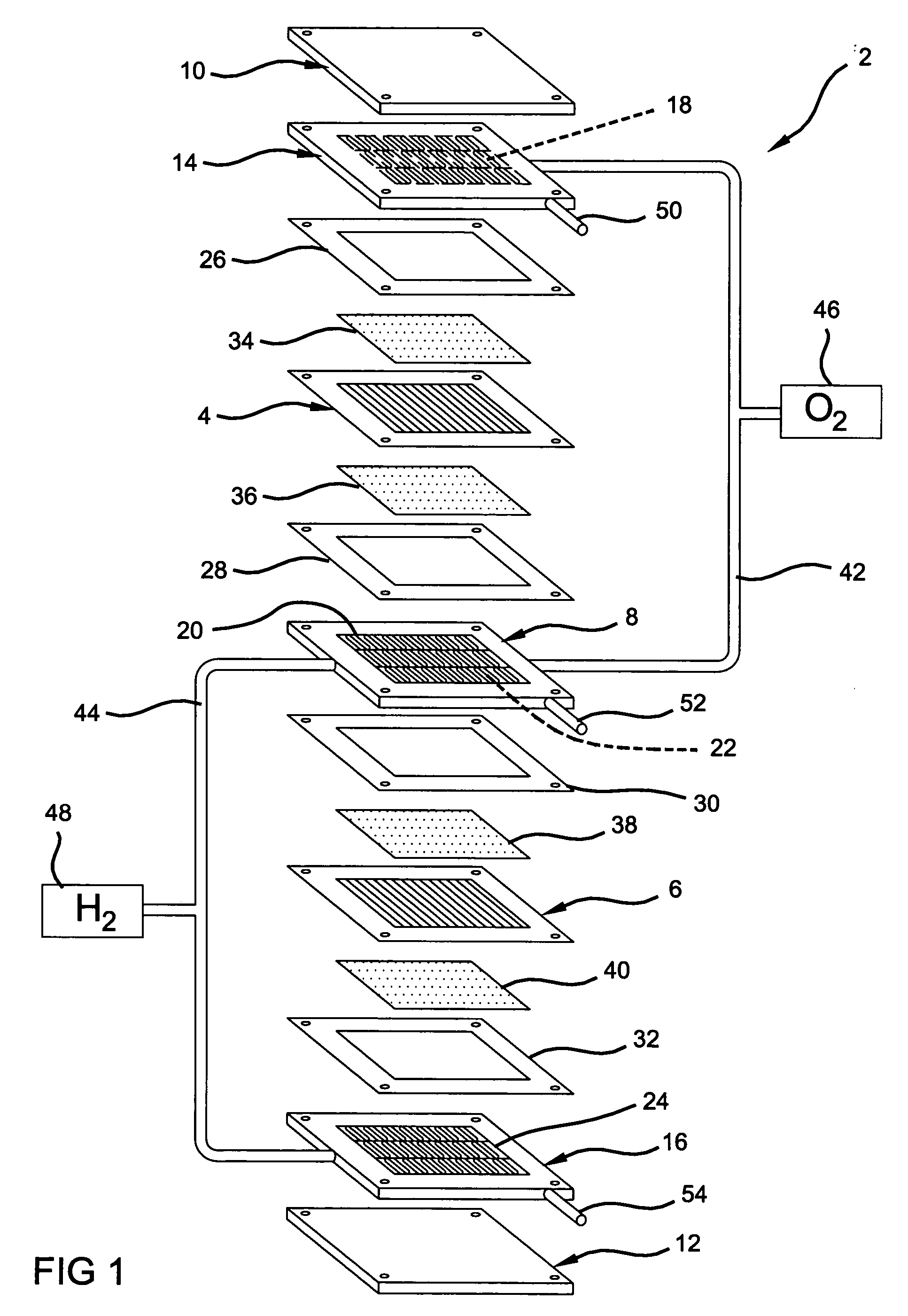
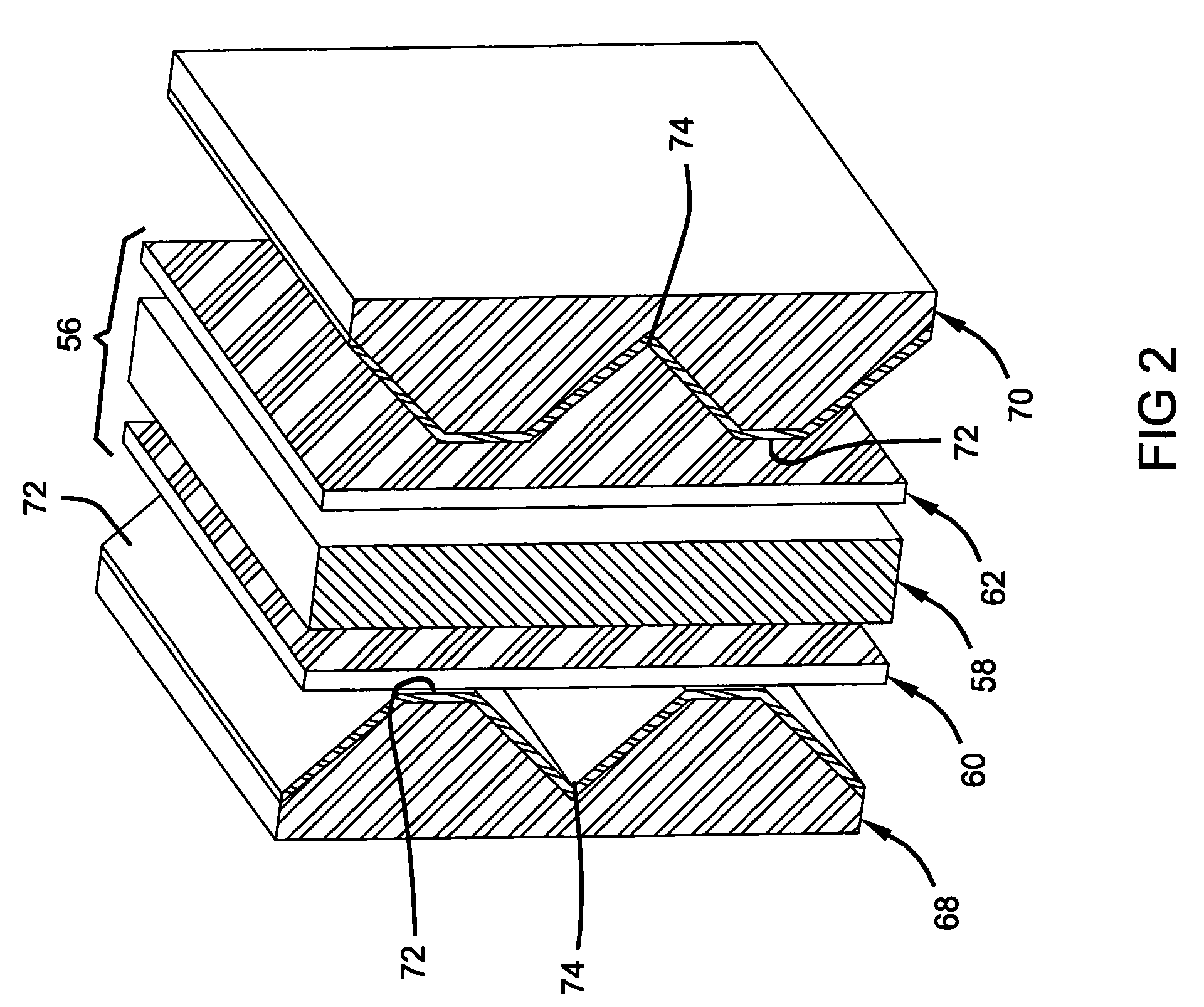
[0021]FIG. 1 depicts a two cell, bipolar fuel cell stack 2 having a pair of membrane-electrode-assemblies (MEAs) 4 and 6 separated from each other by an electrically conductive fluid distribution element 8, hereinafter bipolar plate 8. The MEAs 4 and 6 and bipolar plate 8, are stacked together between clamping plates, or end plates 10 and 12, and end contact elements 14 and 16. The end contact elements 14 and 16, as well as both working faces of the bipolar plate 8, contain a plurality of grooves or channels 18, 20, 22, and 24, respectively, for distributing fuel and oxidant gases (i.e. H2 and O2) to the MEAs 4 and 6.

[0022]Nonconductive gaskets 26, 28, 30, and 32 provide seals and electrical insulation between the several components of the fuel cell stack. Gas permeable conductive materials for diffusion media 34, 36, 3...


PUM

PropertyMeasurementUnit
aspect ratioaaaaaaaaaa
angleaaaaaaaaaa
angleaaaaaaaaaa

Abstract

An assembly for a fuel cell including an electrically conductive fluid distribution element including a flow field disposed on a surface of the element, wherein the flow field includes a plurality of channels for carrying the gaseous reactants of the fuel cell. The assembly also includes an electrically conductive member disposed at the surface of the element to serve as a gas diffusion media. The channels of the element include a plurality of sidewalls formed in various orientations, and the orientations of the side-walls form a cross-sectional geometry of the channel such that water collection regions are formed at an interface of the electrically conductive fluid distribution element and the electrically conductive member, and at a bottom portion of the channel.

Description

FIELD OF THE INVENTION[0001]The present invention relates to a fuel cell. More particularly, the present invention relates to the channel configuration of a flow field on a bipolar plate for a fuel cell.BACKGROUND OF THE INVENTION[0002]Fuel cells have been proposed as a power source for electric vehicles and other applications. One such fuel cell is the PEM (i.e. Proton Exchange Membrane) fuel cell that includes a so-called “membrane-electrode-assembly” (MEA) having a thin, solid polymer membrane-electrolyte having a pair of electrodes (i.e., an anode and a cathode) on opposite faces of the membrane-electrolyte. The MEA is sandwiched between a pair of electrically conductive fluid distribution elements (i.e., bipolar plates) which serve as current collectors for the electrodes, and contain a so-called “flow field” which is an array of lands and grooves formed in the surface of the plate contacting the MEA.[0003]The lands conduct current from the electrodes, while the grooves between...

Claims


Application Information

Patent Timeline
Patent Type & Authority Patents(United States)
IPC IPC(8): H01M2/00H01M2/14H01M8/02H01M8/10H01M2/02H01M8/04
CPCH01M8/04156H01M8/026H01M8/0206H01M8/0228Y02E60/50H01M2008/1095
Inventor TRABOLD, THOMAS AOWEJAN, JON P
Owner GM GLOBAL TECH OPERATIONS LLC
Why Eureka
Try Eureka