GFCI receptacle having blocking means

a ground fault circuit interrupter and receptacle technology, applied in circuit-breaking switches, circuit-breaking switches for excess currents, emergency protective arrangements for limiting excess voltage/current, etc., can solve problems such as tripping of devices, device with inoperative trip mechanism to be reset without ground fault protection, and electricians' difficulty in distinguishing between line side and load side conductors, so as to eliminate the need for bridge contacts

Inactive Publication Date: 2006-08-08
LEVITON MFG
View PDF9 Cites 56 Cited by
  • Summary
  • Abstract
  • Description
  • Claims
  • Application Information

AI Technical Summary

Benefits of technology

[0015]Located within a GFCI device having a receptacle is a movable contact bearing arm which is held in either a closed or open position with a fixed contact by a latching member that is connected to the spring loaded reset button. The reset button assumes a first or a second position which is determined by the conductive state of the GFCI. When the GFC is in a conducting state, the reset button is substantially fully depressed within the housing of the GFCI. When the GFCI is in a non-conductive state, the reset button projects outward beyond the top surface of the housing of the GCFI. Thus, the movable contact bearing arm, acting through a latching member, determines the position of the reset button. A blocking member located within the body of the GFCI is positioned by the reset button to allow free access of the prongs of a plug into the openings of the receptacle when the reset button is depressed or to block at least one opening of the receptacle to prevent a plug from entering the openings of the receptacle when the reset button projects out beyond the surface of the housing. Thus, when the GFCI is in a conducting state, the reset button is recessed within the GFCI housing and positions the blocking member to the first position to allow the prongs of a plug to be inserted into the receptacle openings. When the GFCI is in a non-conducting state, the reset button protrudes outward from the housing of the GFCI to position the blocking member to the second position to block at least one opening of the receptacle to prevent the prongs of a plug from entering the receptacle. GFCI's normally have two separate sets of internally located contacts known as bridge contacts where one set is used to connect a load to the source of electricity and the second set is used to connect a user accessible load to the source of electricity. The bridge contacts provide isolation between the conductors to the load and the conductors to the contacts of the GFCI receptacle when the GFCI is in a fault state. In the GFCI here disclosed, the blocking member prevents the prongs of a plug from entering the receptacle when the GFCI is in a fault state and, therefore, can eliminate the need for the bridge contacts.

Problems solved by technology

However, instances may arise where an abnormal condition such as a lightning strike may result not only in a surge of electricity at the device which can cause a tripping of the device but can also disable the trip mechanism used to cause the mechanical breaking of the circuit.
Under such circumstances an unknowing user, faced with a GFCI which has tripped, may press the reset button which, in turn, will cause the device with an inoperative trip mechanism to be reset without the ground fault protection being available.
However, instances may occur where the circuit interrupting device is improperly connected to the external wires so that the load wires are connected to the line side connection and the line wires are connected to the load connection.
Such wiring is prevalent in new construction, where power is not yet provided to the residence branch circuits and the electrician has difficulty in distinguishing between the line side and load side conductors.
In the event the circuit interrupting device is reverse wired, the user accessible load connection may not be protected, even if fault protection to the load side connection remains.

Method used


Image

  • GFCI receptacle having blocking means
  • GFCI receptacle having blocking means
  • GFCI receptacle having blocking means

Examples


Embodiment Construction

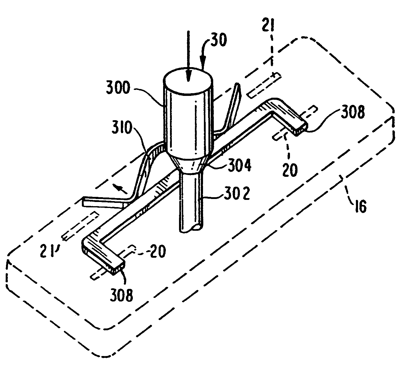
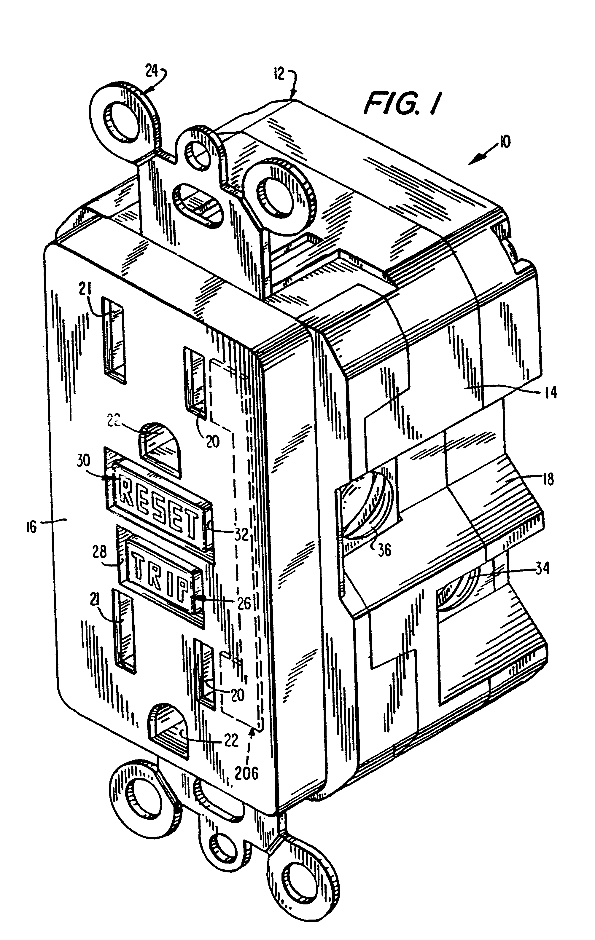
[0024]The present application contemplates various types of circuit interrupting devices that are capable of breaking at least one conductive path at both a line side and a load side of the device. The conductive path is typically divided between a line side that connects to supplied electrical power and a load side that connects to one or more loads. The term resettable circuit interrupting devices include ground fault circuit interrupters (GFCI's), arc fault circuit interrupters (AFCI's), immersion detection circuit interrupters (IDCI's), appliances leakage circuit interrupters (ALCI's), and equipment leakage circuit interrupters (ELCI's) which have a receptacle for receiving a plug.

[0025]For the purpose of the present application, the structure or mechanisms used in the circuit interrupting devices, shown in the drawings and described below, are incorporated into a GFCI protected receptacle which can receive at least one plug and is suitable for installation in a single gang junc...


PUM


Abstract

Located within a GFCI device having a receptacle is a movable contact bearing arm which is held in either a closed or open position with a fixed contact by a latching member that is connected to the spring loaded reset button. The reset button assumes a first or a second position which is determined by the conductive state of the GFCI. When the GFC is in a conducting state, the reset button is substantially fully depressed within the housing of the GFCI. When the GFCI is in a non-conductive state, the reset button projects outward beyond the top surface of the housing of the GCFI. Thus, the movable contact bearing arm, acting through a latching member, determines the position of the reset button. A blocking member located within the body of the GFCI is positioned by the reset button to allow free access of the prongs of a plug into the openings of the receptacle when the reset button is depressed or to block at least one opening of the receptacle to prevent a plug from entering the openings of the receptacle when the reset button projects out beyond the surface of the housing. Thus, when the GFCI is in a conducting state, the reset button is recessed within the GFCI housing and positions the blocking member to the first position to allow the prongs of a plug to be inserted into the receptacle openings. When the GFCI is in a non-conducting state, the reset button protrudes outward from the housing of the GFCI to position the blocking member to the second position to block at least one opening of the receptacle to prevent the prongs of a plug from entering the receptacle. GFCI's normally have two separate sets of internally located contacts known as bridge contacts where one set is used to connect a load to the source of electricity and the second set is used to connect a user accessible load to the source of electricity. The bridge contacts provide isolation between the conductors to the load and the conductors to the contacts of the GFCI receptacle when the GFCI is in a fault state. In the GFCI here disclosed, the blocking member prevents the prongs of a plug from entering the receptacle when the GFCI is in a fault state and, therefore, can eliminate the need for the bridge contacts.

Description

[0001]This application is a continuation of application Ser. No. 10 / 839,947, filed May 6, 2004, now U.S. Pat. No. 6,873,231, which is a continuation of application Ser. No. 10 / 334,182, filed Dec. 30, 2002, now U.S. Pat. No. 6,734,769.BACKGROUND OF THE INVENTION[0002]1. Field[0003]The present invention relates generally to resettable circuit interrupting devices and systems and more particularly to a ground fault circuit interrupter (GFCI) device and receptacle having plug blocking means.[0004]2. Description of the Related Art[0005]Many electrical wiring devices have a line side, which is connectable to an electrical power supply, a load side which is connectable to one or more loads and at least one conductive path between the line and load sides. Electrical connections to wires supplying electrical power or wires conducting electricity to one or more loads can be at the line side and load side connections. The electrical wiring device industry has witnessed an increasing call for c...

Claims


Application Information

Patent Timeline
Patent Type & Authority Patents(United States)
IPC IPC(8): H01H73/00H01R13/44H01H83/04H02H3/33
CPCH01H83/04H02H3/338H01R13/44
Inventor GERMAIN, FRANTZSTEWART, STEPHEN
Owner LEVITON MFG
Why Eureka
Try Eureka