On-chip multiple tap transformer and inductor

a multiple tap transformer and inductor technology, applied in the field of radio communication technology, can solve the problems of low quality, limited integration, and large size and resistan

Inactive Publication Date: 2006-08-08
AVAGO TECH INT SALES PTE LTD
View PDF7 Cites 31 Cited by
  • Summary
  • Abstract
  • Description
  • Claims
  • Application Information

AI Technical Summary

Benefits of technology

[0011]The on-chip multiple tap transformer and inductor of the present invention substantially meets these needs and others. One embodiment of an on-chip multiple tap transformer balun in accordance with the present invention includes a 1st winding and a 2nd winding having two portions. The 1st winding is on a 1st layer of an integrated circuit and is operably coupled for a single ended signal. The 1st and 2nd portions of the 2nd winding are on a 2nd layer of the integrated circuit. The 1st portion of the 2nd winding includes a 1st node, a 2nd node, and a tap. The 1st node is operably coupled to receive a 1st leg of a 1st differential signal and the 2nd node is coupled to a reference potential. The tap of the 1st portion is operably coupl...

Problems solved by technology

However, such integration has been limited due to flux leakage, capacitive coupling limits, and significant series resistance.
While coplanar interleaved transformers reduces size and resistance and are widely used, they suffer from low quality (Q) factor, small coupling coefficients, and, if used as a balun, the center tap is often at an undesirable location, resulting in an asymmetric geometry.
As is known, asymmetry of a transformer winding causes an imbalance in the resulting differential signal and/or an imbalance in the res...

Method used


Image

  • On-chip multiple tap transformer and inductor
  • On-chip multiple tap transformer and inductor
  • On-chip multiple tap transformer and inductor

Examples


Embodiment Construction

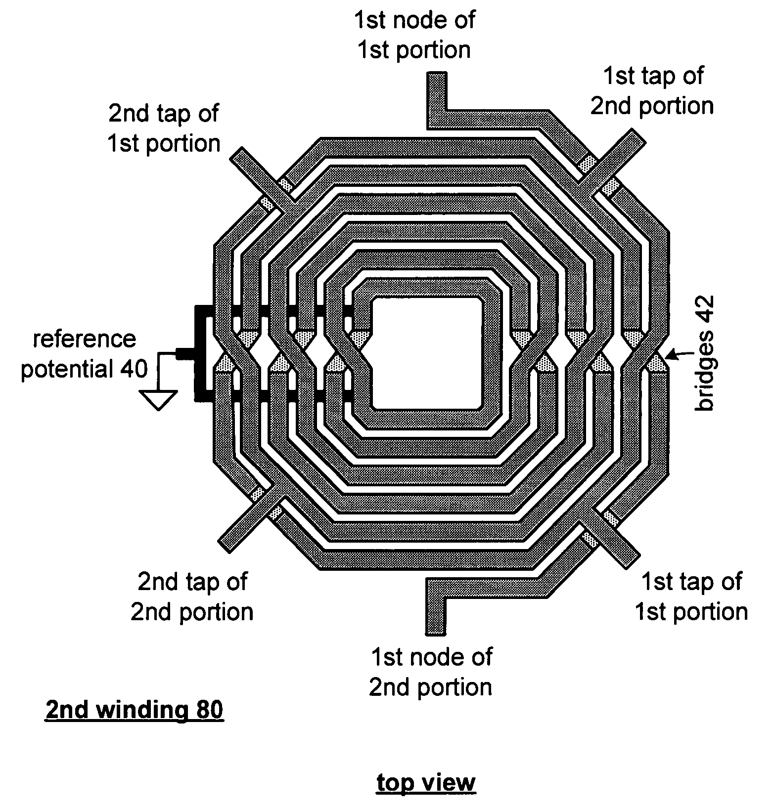
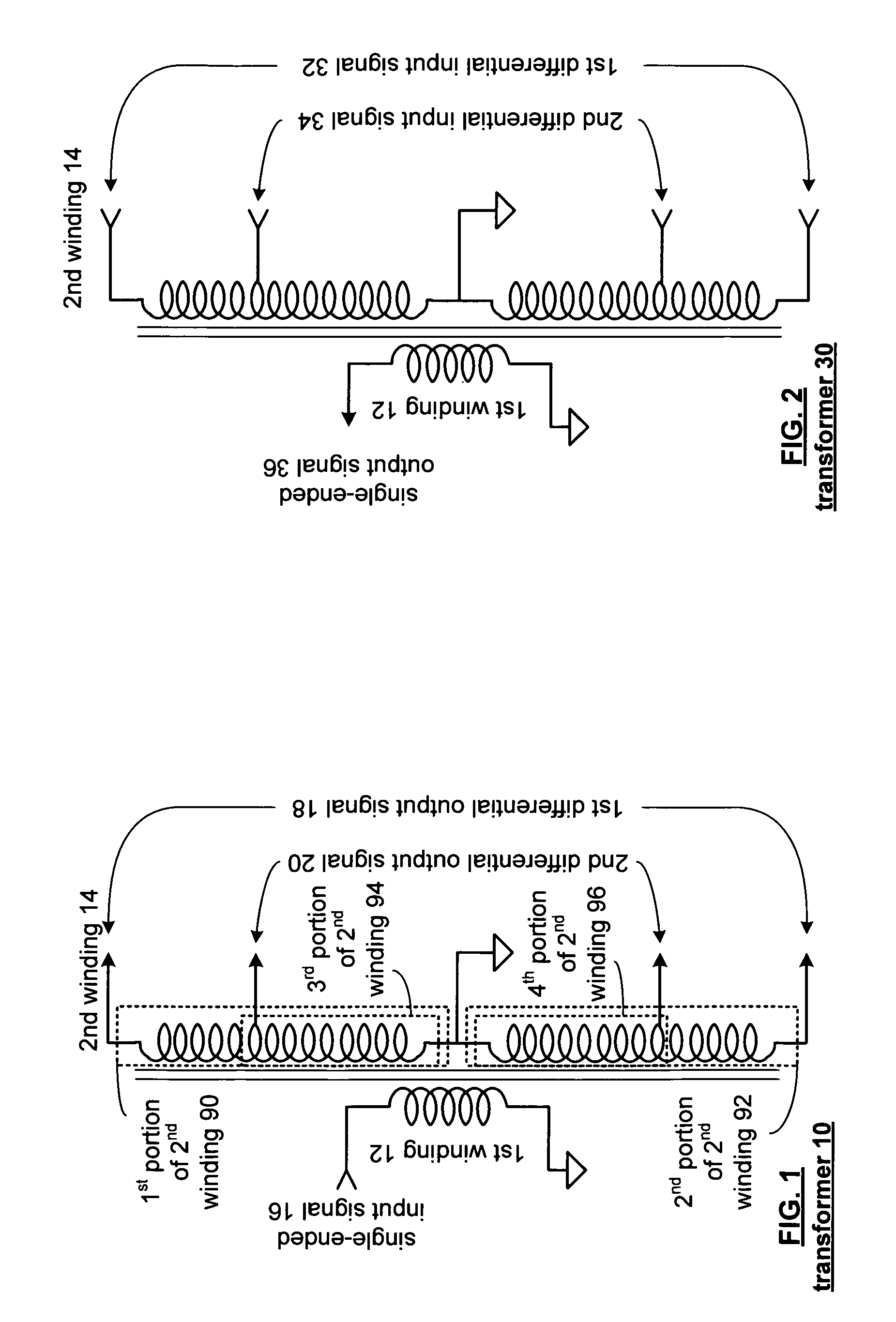
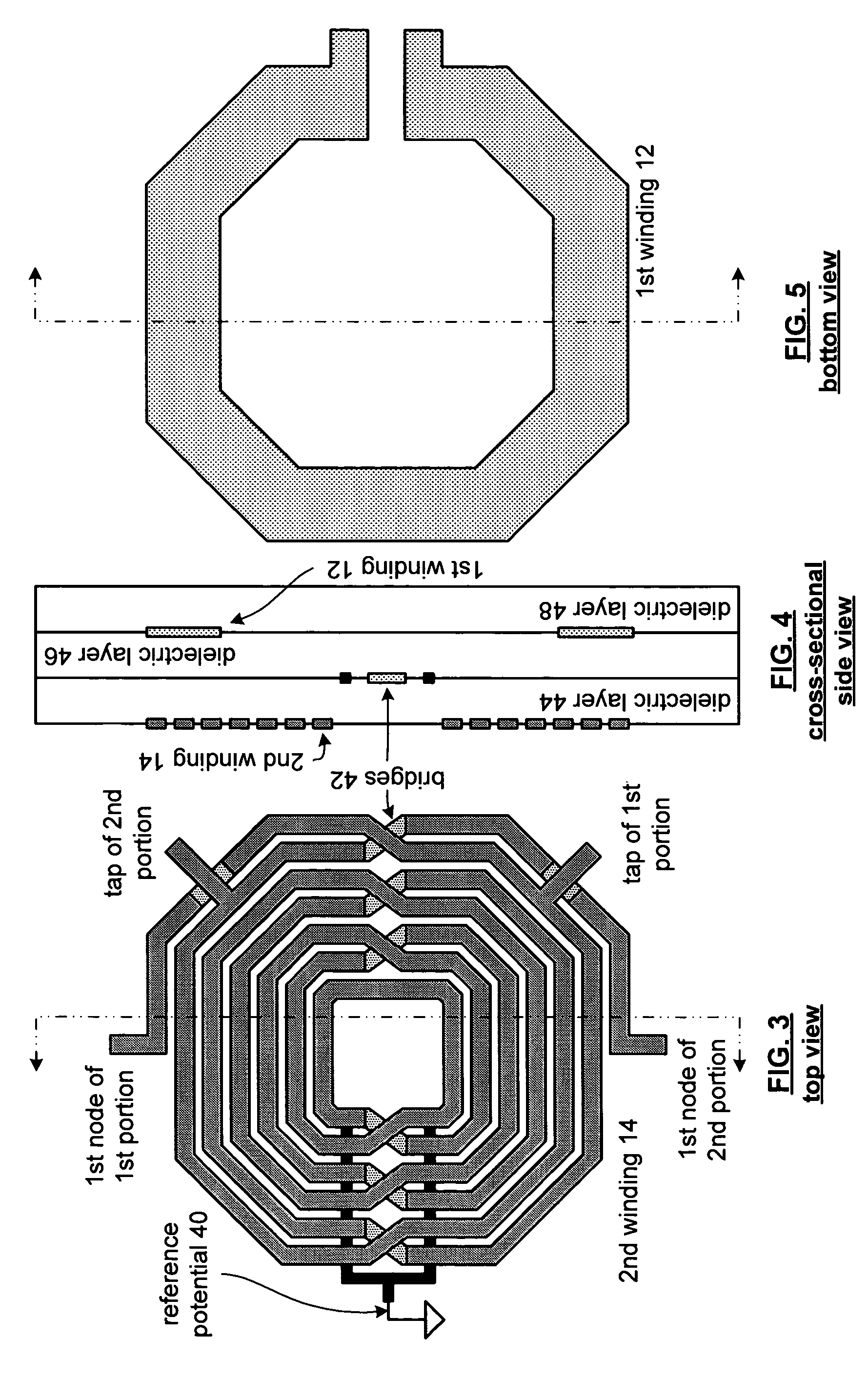
[0025]FIG. 1 is a schematic diagram of an on-chip multi-tap transformer balun 10 that is operably coupled to convert a single ended input signal 16 into a 1st differential output signal 18 and a 2nd differential output signal 20. The transformer 10 includes a 1st winding 12 and a 2nd winding 14. The 2nd winding includes a 1st portion 90 and a 2nd portion 92 each of which includes two nodes and a tap. The common nodes of the 1st portion 90 and 2nd portion 92 of the 2nd winding 14 are operably coupled to a reference potential (e.g., AC ground). The taps of the 1st portion 90 and 2nd portion 92 of the 2nd winding 14 are operably coupled to produce the 2nd differential output signal 20 across the 3rd portion 94 and 4th portion 96 of the 2nd winding 14. The 1st nodes of the 1st and 2nd portions, 90 and 92, of the 2nd winding 14 are operably coupled to produce the 1st differential output signal 18.

[0026]The taps are symmetrical with respect to the node coupled to the AC ground reference p...


PUM


Abstract

An on-chip multiple tap transformer balun includes a 1st winding and a 2nd winding having two portions. The 1st winding is on a 1st layer of an integrated circuit and is operably coupled for a single ended signal. The 1st and 2nd portions of the 2nd winding are on a 2nd layer of the integrated circuit. The 1st portion of the 2nd winding includes a 1st node, a 2nd node, and a tap. The 1st node is operably coupled to receive a 1st leg of a 1st differential signal and the 2nd node is coupled to a reference potential. The tap of the 1st portion is operably coupled for a 1st leg of a 2nd differential signal. The 2nd portion of the 2nd winding includes a 1st node, 2nd node, and tap. The 1st node is operably coupled to receive a 2nd leg of the 1st differential signal and the 2nd node is operably coupled to the reference potential. The tap of the 2nd portion is coupled for a 2nd leg of the 2nd differential signal. The 1st and 2nd portions of the 2nd winding are symmetrical with respect to the 1st and 2nd nodes and with respect to the tap nodes.

Description

[0001]This patent application is claiming priority under 35 USC § 120 to co-pending patent application entitled ON-CHIP MULTIPLE TAP TRANSFORMER AND INDUCTOR having a Ser. No. 10 / 200,990 and a filing date of Jul. 23, 2002.BACKGROUND OF THE INVENTION[0002]1. Technical Field of the Invention[0003]This invention relates generally to radio communication technology and more particularly to transformers used within the radio communication technology.[0004]2. Description of Related Art[0005]Two-way radios, which may be incorporated in wireless communication devices, are known to include an antenna, a transformer, an antenna switch, a receiver section, and a transmitter section. The antenna switch couples either the receiver section or the transmitter section to the antenna via the transformer. The transformer may be a transformer balun (balanced / unbalanced) and is generally used to convert single ended signals into differential signals and conversely to convert differential signals into si...

Claims


Application Information

Patent Timeline
IPC IPC(8): H01F5/00H01F17/00H01F21/12H01L27/08H03H7/42
CPCH01F17/0006H01F21/12H03H7/42H01L27/08H01F2021/125
Inventor CASTANEDA, JESUS A.ROGOUGARAN, RAZIEHBHATTI, IQBAL S.YANG, HUNG YU
Owner AVAGO TECH INT SALES PTE LTD
Why Eureka
Try Eureka