Method and apparatus for determining absolute position of a tip of an elongate object on a plane surface with invariant features

a technology of invariant features and elongates, applied in the direction of instruments, angle measurement, counting objects on conveyors, etc., can solve the problems of cumbersome user, difficult to handle, and no such devices are as user-friendly and accepted as pen and paper

Active Publication Date: 2006-08-08
ELECTRONICS SCRIPTING PRODS
View PDF71 Cites 175 Cited by
  • Summary
  • Abstract
  • Description
  • Claims
  • Application Information

AI Technical Summary

Problems solved by technology

The challenge of communicating with electronic devices is in the very input interface to the electronic device.
Unfortunately, none of these devices are as user-friendly and accepted as pen and paper.
Although the above-referenced teachings provide a number of approaches they are cumbersome to the user.
Many of these approaches provide the user with pens that are difficult to handle, impose special writing and / or monitoring conditions and / or they require cumbersome auxiliary systems and devices to track and digitize the information written on the writing surface.
Thus, the problem of a user-friendly input interface based on a writing implement has not been solved.

Method used


Image

  • Method and apparatus for determining absolute position of a tip of an elongate object on a plane surface with invariant features
  • Method and apparatus for determining absolute position of a tip of an elongate object on a plane surface with invariant features
  • Method and apparatus for determining absolute position of a tip of an elongate object on a plane surface with invariant features

Examples


Embodiment Construction

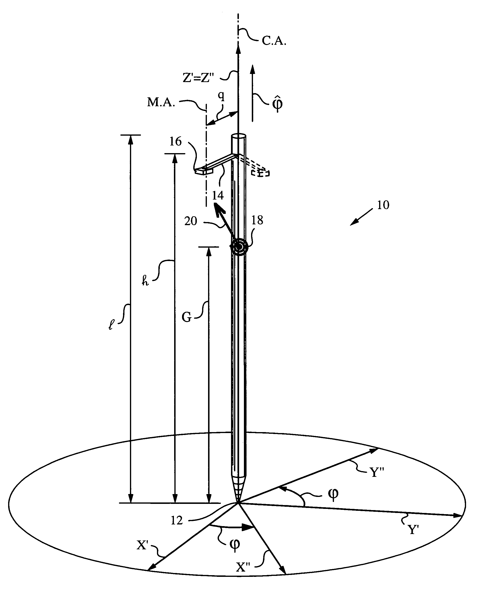
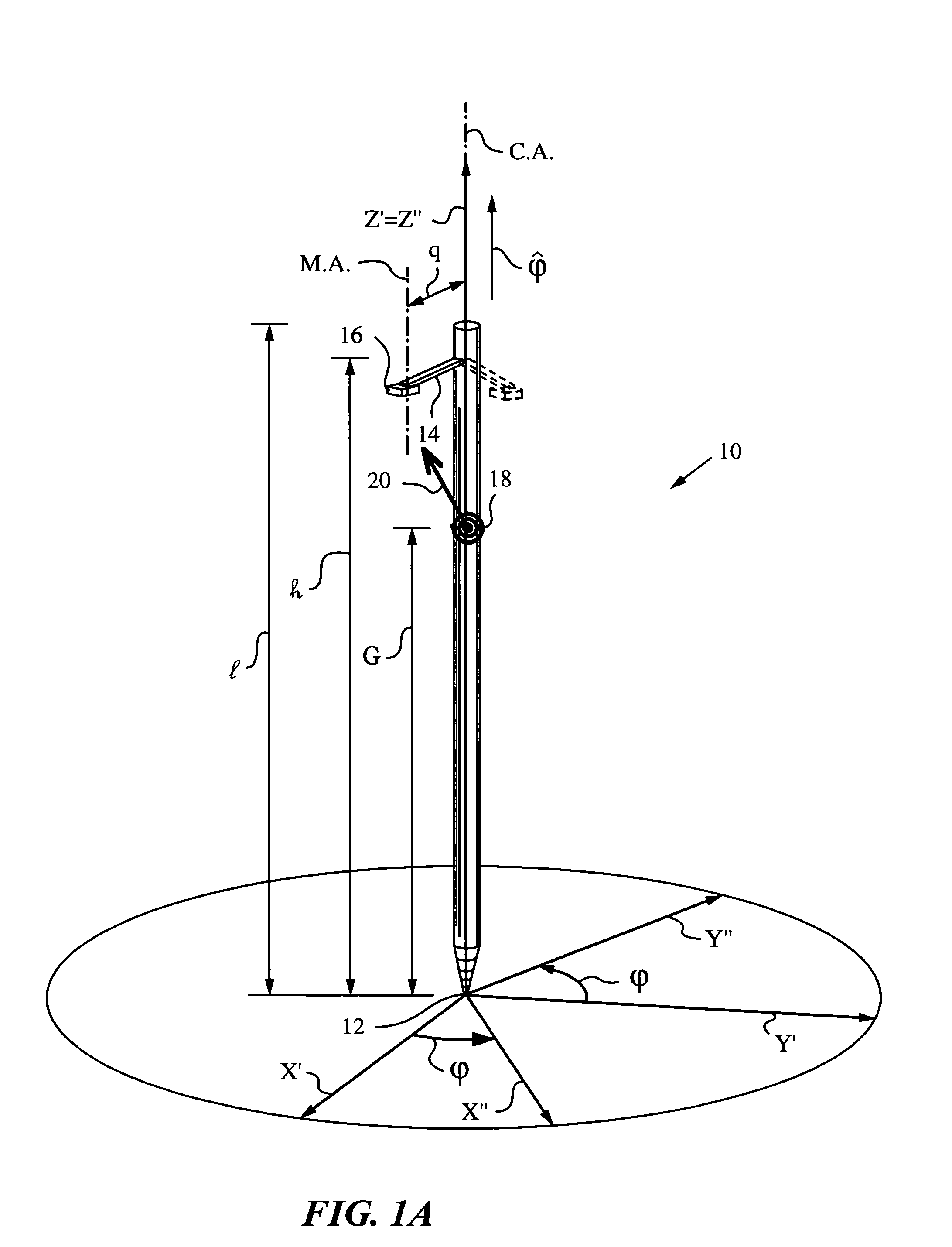
[0069]The present invention will be best understood by initially reviewing Euler rotations as used herein to describe the pose of an elongate object. FIG. 1A illustrates an elongate object 10 of length l with a tip 12 at the origin of non-rotated object coordinates (X′,Y′,Z′). An axis of object 10, in the present embodiment a center line or center axis denoted by C.A. is collinear with the Z′ axis. Axis C.A. passes through tip 12 and the origin of non-rotated object coordinates (X′,Y′,Z′). A scan arm 14 of length q is mounted on object 10 at a height h perpendicular to axis C.A. Scan arm 14 carries a scan mirror 16 having a mirror axis M.A. that is parallel to axis C.A. when scan mirror 16 is in the resting or neutral position. A source or emitter 18 is mounted at height G for delivering a probe radiation 20 to scan mirror 16.

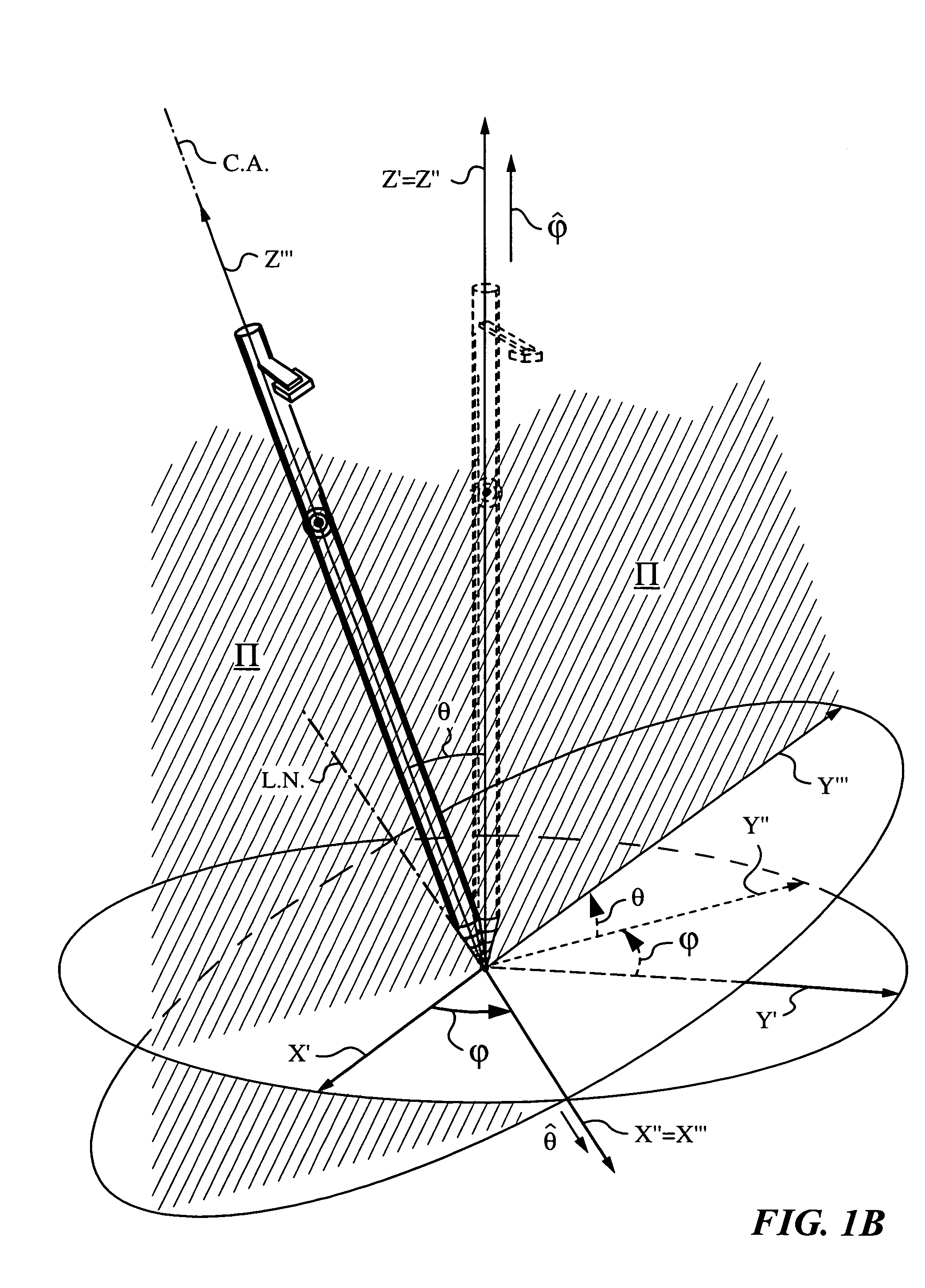
[0070]A person skilled in the art will appreciate that many conventions exist for describing rotations of object 10. In the convention adopted herein, scan arm...


PUM


Abstract

A method and apparatus for determining a pose of an elongate object and an absolute position of its tip while the tip is in contact with a plane surface having invariant features. The surface and features are illuminated with a probe radiation and a scattered portion, e.g., the back-scattered portion, of the probe radiation returning from the plane surface and the feature to the elongate object at an angle τ with respect to an axis of the object is detected. The pose is derived from a response of the scattered portion to the surface and the features and the absolute position of the tip on the surface is obtained from the pose and knowledge about the feature. The probe radiation can be directed from the object to the surface at an angle σ to the axis of the object in the form of a scan beam. The scan beam can be made to follow a scan pattern with the aid of a scanning arrangement with one or more arms and one or more uniaxial or biaxial scanners. Angle τ can also be varied, e.g., with the aid of a separate or the same scanning arrangement as used to direct probe radiation to the surface. The object can be a pointer, a robotic arm, a cane or a jotting implement such as a pen, and the features can be edges, micro-structure or macro-structure belonging to, deposited on or attached to the surface which the tip of the object is contacting.

Description

FIELD OF THE INVENTION[0001]The present invention relates generally to determining a pose of an elongate object and an absolute position of its tip on a plane surface with invariant features and it applies in particular to elongate objects such as a pointers or jotting implements.BACKGROUND OF THE INVENTION[0002]When an object moves with respect to stationary references such as a ground plane, fixed points, lines or reference surfaces, knowledge of the object's absolute position with respect to these references can be used to derive a variety of its parameters of motion as well as its pose and absolute position with respect to any of these stationary references. Over time, many useful coordinate systems and methods have been developed to track the pose and absolute position of objects and to parameterize their equations of motion. For a theoretical background the reader is referred to textbooks on classical mechanics such as Goldstein et al., Classical Mechanics, 3rd Edition, Addiso...

Claims


Application Information

Patent Timeline
Patent Type & Authority Patents(United States)
IPC IPC(8): G01B11/26G06F3/03G06M7/00
CPCG06F3/03545G06F3/0317G06F3/0321G06F3/03G06F3/0354G06K11/06
Inventor BUERMANN, DALE H.MANDELLA, MICHAEL J.CARL, STEWART R.ZHANG, GUANGHUA G.GONZALEZ-BANOS, HECTOR H.
Owner ELECTRONICS SCRIPTING PRODS
Why Eureka
Try Eureka