Lens barrel having a lens barrier mechanism

a technology of lens barrel and lens barrier, which is applied in the field of lens barrel, can solve the problem of large inner diameter of the exterior ring member, and achieve the effect of not complicating the structure of the lens barrier mechanism

Inactive Publication Date: 2006-08-08
ASAHI KOGAKU KOGYO KK
View PDF16 Cites 10 Cited by
  • Summary
  • Abstract
  • Description
  • Claims
  • Application Information

AI Technical Summary

Benefits of technology

[0009]The present invention provides a lens barrel having a lens barrier mechanism fixed to a ring member, wherein the ring member is successfully formed to have a large inner diameter with a minimum increase of the outer diameter of the ring member so that the lens barrier mechanism having a large diameter can be fixed to the ring member. The present invention further provides a lens barrel having a lens barrier mechanism, wherein the lens barrier mechanism fixed to a ring member is successfully provided with a set of long barrier blades without an increase of the diameter of the ring member and without complicating the structure of the lens barrier mechanism.

Problems solved by technology

However, the inner diameter of the exterior ring member has to be large if the diameter of the lens barrier mechanism is large.

Method used


Image

  • Lens barrel having a lens barrier mechanism
  • Lens barrel having a lens barrier mechanism
  • Lens barrel having a lens barrier mechanism

Examples


Embodiment Construction

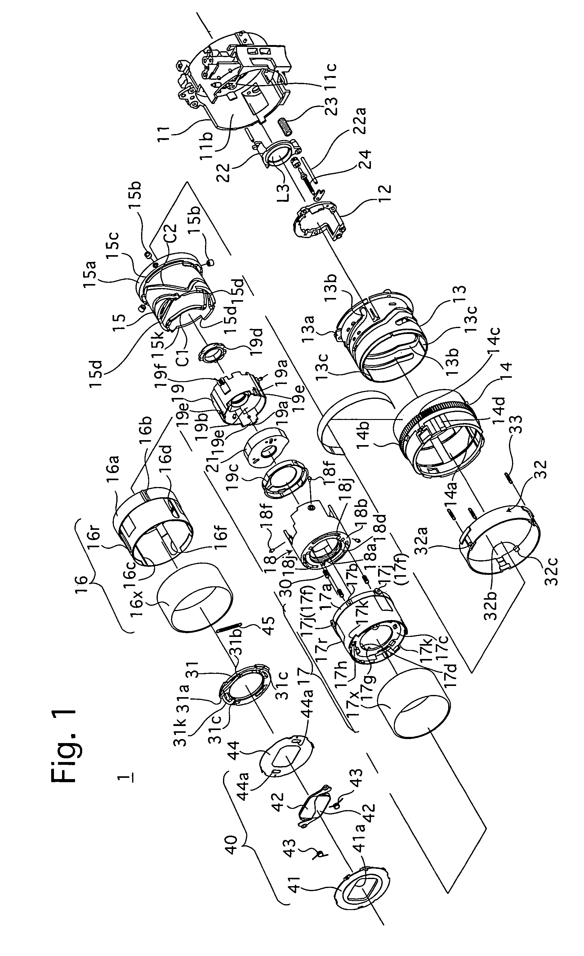
[0048]FIG. 1 is an exploded perspective view of an embodiment of an extendable zoom lens barrel for a digital camera.

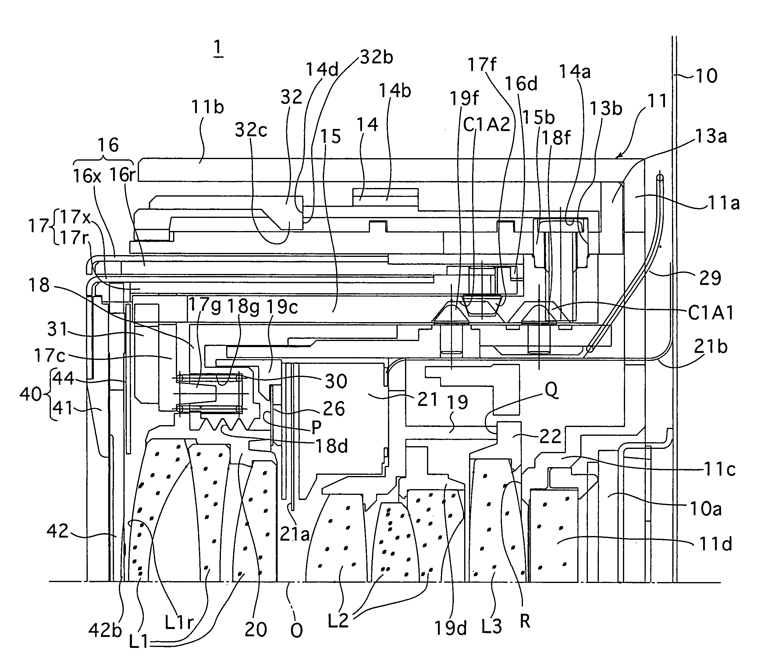
[0049]The zoom lens barrel 1 is provided with a lens-drive cam mechanism which includes a set of three lens-drive cam grooves C1 formed on a cam ring 15, a set of three follower pins 18f fixed to a first lens group moving frame (movable lens frame) 18, a set of three follower pins 19f fixed to a second lens group moving frame 19, a set of three linear guide bosses 17d (only one of them appears in FIGS. 1 and 3) of an inner ring 17, a set of three linear guide holes 18a of the first lens group moving frame 18, and a set of three linear guide grooves 18c of the first lens group moving frame 18 and a set of three linear guide keys 19a of the second lens group moving frame 19. The zoom lens barrel 1 is further provided with a ring-drive cam mechanism which includes a set of three cam grooves C2 formed on the cam ring 15, a set of three follower pins 17f (only one of them ...


PUM


Abstract

A lens barrel includes a guide barrel, an outer ring, an inner ring, a cam ring and a movable lens frame, arranged in that order from outermost side, wherein the axes thereof coincide with a common optical axis, the outer ring being guided linearly in the optical axis direction by the stationary barrel, the inner ring being linearly guided in the optical axis direction by the outer ring, and the cam ring being rotatable to move the movable lens frame in the optical axis direction; and a lens barrier mechanism having an aperture positioned in front of the movable lens frame, the lens barrier mechanism being provided on a front opening of the inner ring, for opening and closing the aperture.

Description

[0001]This is a Continuation Application of U.S. application Ser. No. 10 / 101,727, filed Mar. 21, 2002, now U.S. Pat. No. 6,788,475 the contents of which are expressly incorporated by reference herein in its entirety.BACKGROUND OF THE INVENTION[0002]1. Field of the Invention[0003]The present invention relates to a lens barrel provided at the front end thereof with a lens barrier mechanism which is driven to open and close its barrier blades for protecting the frontmost lens surface from being stained or damaged.[0004]2. Description of the Related Art[0005]As an example of a conventional lens barrel having a lens barrier mechanism, a lens barrel which is provided therein with a stationary ring, a rotating cam ring positioned inside the stationary ring, and an exterior ring member positioned between the stationary ring and the cam ring, is known in the art. The cam ring is provided with a set of follower pins, and the exterior ring member is provided with a corresponding set of cam gro...

Claims


Application Information

Patent Timeline
Patent Type & Authority Patents(United States)
IPC IPC(8): G02B15/14G02B7/02G02B7/10
CPCG02B7/102
Inventor NOMURA, HIROSHIYAMAZAKI, YOSHIHIROOKUDA, ISAONAKAMURA, SATORU
Owner ASAHI KOGAKU KOGYO KK
Why Eureka
Try Eureka