
Translator for IP networks, network system using the translator, and IP network coupling method therefor

a translator and network technology, applied in the field of internet protocol (ip) network coupling, translator for ip network, and network system, can solve the problems of inability to replace the previous network protocol with ipv6 in all existing nodes, and the coexistence of ipv4 nodes and ipv6 nodes for a long tim

Inactive Publication Date: 2006-08-08
HITACHI LTD
View PDF12 Cites 28 Cited by
  • Summary
  • Abstract
  • Description
  • Claims
  • Application Information

AI Technical Summary

Benefits of technology

The present invention provides an IP network coupling method that allows two networks to be mutually coupled through a translator without exhausting IP addresses used in one of the networks. The method assigns different IP addresses to devices in each network, and communicates between devices using the assigned addresses. This ensures that the same IP address is not assigned to two or more devices in each network, and avoids conflicts between the networks. The use of the method allows for the coexistence of IPv4 and IPv6 nodes in a single network for a long time.

Problems solved by technology

Although the IPv6 has extended fields for storing the IP addresses, additional modifications partially added to the header and associated processing give rise to another problem that the IPv6 is not compatible with the existing IPv4.
However, since simultaneous replacement of the previous network protocol with the IPv6 in all existing nodes is actually impossible, it is anticipated that coexistence of IPv4 nodes and IPv6 nodes will last for a long time.
However, since the IPv6 and the IPv4 employ different header formats and so on from each other, IPv6 nodes and IPv4 nodes cannot be simply coupled.

Method used


Image

  • Translator for IP networks, network system using the translator, and IP network coupling method therefor
  • Translator for IP networks, network system using the translator, and IP network coupling method therefor
  • Translator for IP networks, network system using the translator, and IP network coupling method therefor

Examples


Embodiment Construction

[0055]Embodiments of the present invention will hereinafter be described with reference to the accompanying drawings.

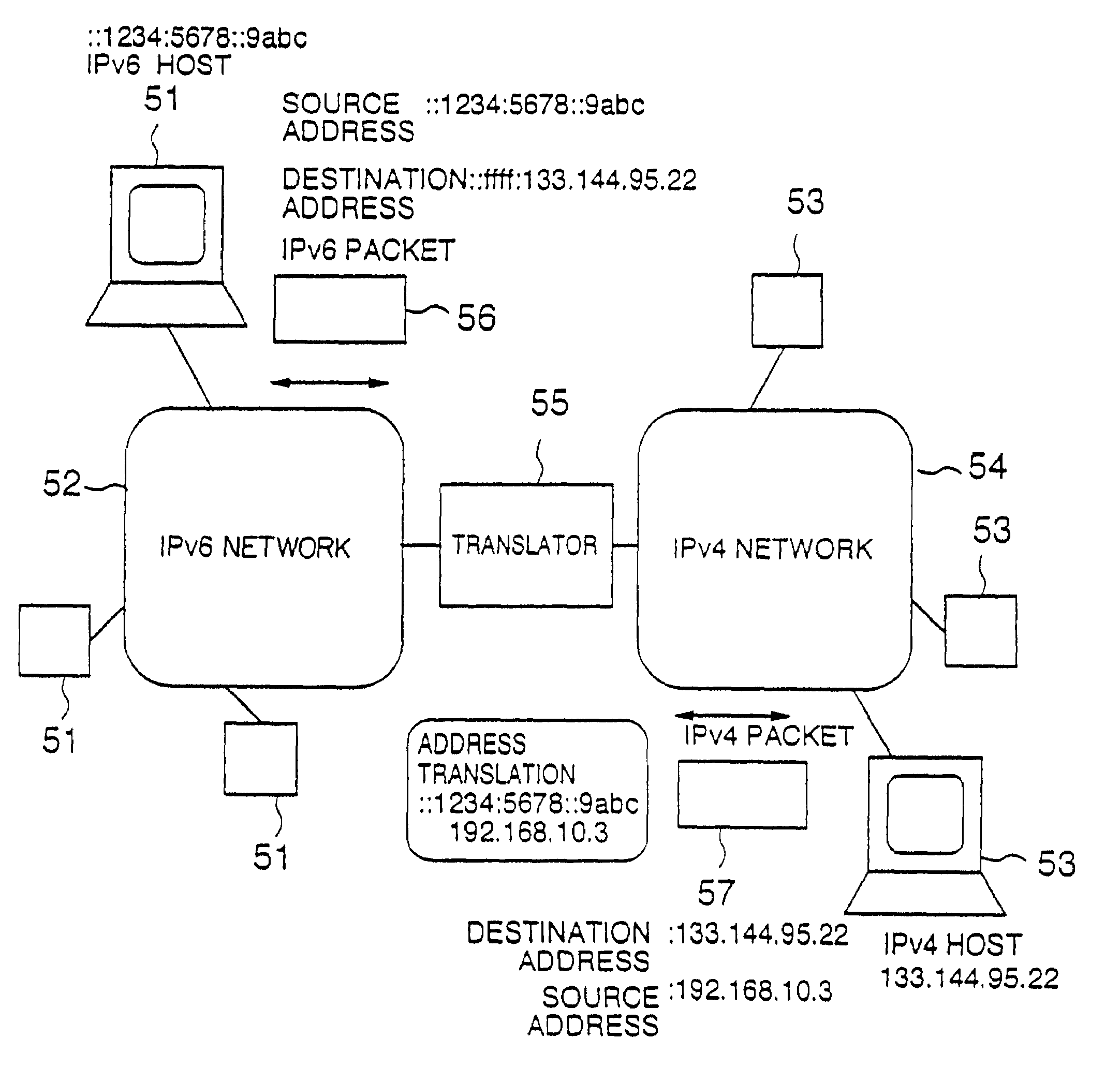
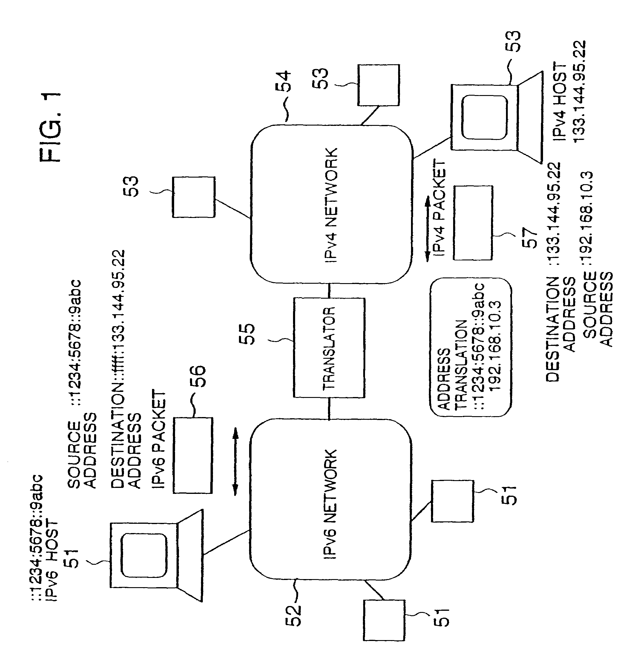
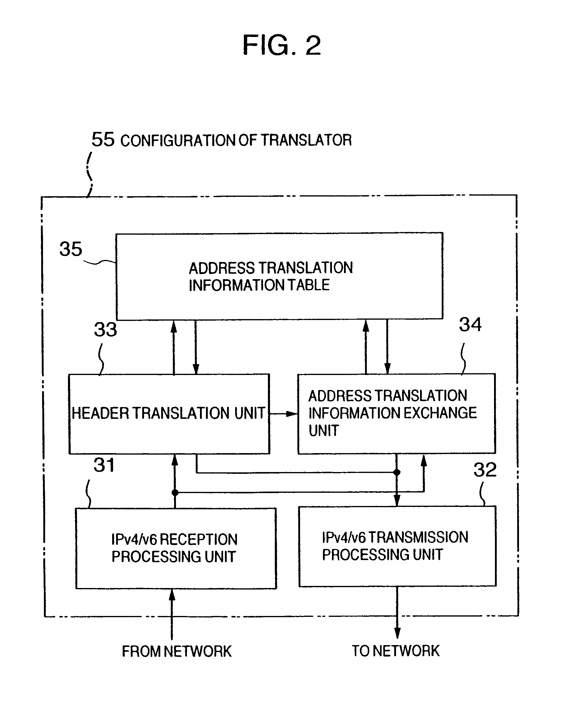
[0056]As illustrated in FIG. 1, an embodiment of the present invention assumes an environment which allows coexistence of an IPv6 network 52 to which a plurality of IPv6 hosts 51 are connected and an IPv4 network 54 in which a plurality of IPv4 hosts 53 are connected, where these networks are interconnected through an IPv6 / IPv4 translator 55 (hereinafter called “translator 55”). In the IPv6 network 52, a data is transferred through a packet having the IPv6 header shown in FIG. 11A (hereinafter called “IPv6 packet”). In the header of the IPv6 packet, an IPv6 host 51 is represented by a normal IPv6 address, while an IPv4 host 53 is represented by an IPv4-mapped-IPv6 address (FIG. 12B). In the IPv4 network 54, a data is transferred through a packet having the IPv4 header shown in FIG. 11B (hereinafter called “IPv4 packet”). In the header of the IPv4 packet, the translato...


PUM


Abstract

A translator for coupling a first network such as an internet protocol version 4 (IPv4) and a second network such as an internet protocol version 6 (IPv6) having different addressing architectures for IP addresses due to a difference in version or the like so as not to exhaust the IP addresses of one of the two networks, a network system using the translator, and a network coupling method therefor are provided. When a packet is transferred from the IPv6 network to the IPv4 network, the translator assigns any of a plurality of previously prepared IPv4 addresses to an IPv6 address stored in a source storing field of the IPv6 packet. The assigned address is stored in a source storing field of an IPv4 packet. A packet translation unit is provided for assigning the foregoing IPv6 address to an IPv4 address stored in a destination storing field of the IPv4 packet, when a packet is transferred from the IPv4 network to the IPv6 network, and for storing this address in a destination storing field of the IPv6 packet.

Description

CROSS-REFERENCE TO RELATED APPLICATION[0001]The present application is a continuation of U.S. application Ser. No. 08 / 887,123, filed Jul. 2, 1997 now U.S. Pat. No. 6,038,233, and is hereby incorporated by reference.BACKGROUND OF THE INVENTION[0002]The present invention relates to an internet protocol (IP) network coupling method, a translator for IP networks, and a network system using the translator which are intended to couple a first class IP network in which a plurality of devices of interest are assigned IP addresses of a first class so as to prevent the assignment of the same IP address to different devices and a second class IP network in which a plurality of devices of interest are assigned IP addresses of a second class so as to prevent the assignment of the same IP address to different devices.[0003]The protocol most widely known at present as a protocol for network layers used in the TCP / IP communication is the internet protocol (IP). The IP functions to provide an addres...

Claims


Application Information

Patent Timeline
Patent Type & Authority Patents(United States)
IPC IPC(8): H04L12/66H04L29/06H04L29/12
CPCH04L29/12358H04L61/251H04L69/167H04L69/16H04L69/22H04L29/12462H04L29/12801H04L61/6004H04L69/08H04L61/255H04L2101/604
Inventor HAMAMOTO, SHINICHIWATANABE, KENTSUCHIYA, KAZUAKIIKEDA, NAOYA
Owner HITACHI LTD
Learn More