Video transcoder with drift compensation

a video transcoder and drift compensation technology, applied in the field of video transcoders with drift compensation, can solve the problems of low quality of bitstreams, low efficiency of transcoding, and inability to achieve full decoding and full encoding in transcoders,

Inactive Publication Date: 2006-08-08
MITSUBISHI ELECTRIC RES LAB INC
View PDF9 Cites 25 Cited by
  • Summary
  • Abstract
  • Description
  • Claims
  • Application Information

AI Technical Summary

Problems solved by technology

Also, there is a significant amount of error resilience features built into this standard to allow for robust transmission across error-prone channels, such as wireless channels.
In practice, full decoding and full encoding in a transcoder is not done due to the high complexity of encoding the decoded bitstream.
It should be noted these methods produce bitstreams at a reduced spatial resolution reduction that lack quality, or are accomplished with high complexity.
Also, proper consideration has not been given to the means by which reconstructed macroblocks are formed.
Moreover, these methods do not specify any architectural details.
No methods have been described to perform rate control on the reduced resolution blocks.
It is inefficient to always use the 1:1 mapping because more bits are used to code four motion vectors.

Method used


Image

  • Video transcoder with drift compensation
  • Video transcoder with drift compensation
  • Video transcoder with drift compensation

Examples


first embodiment

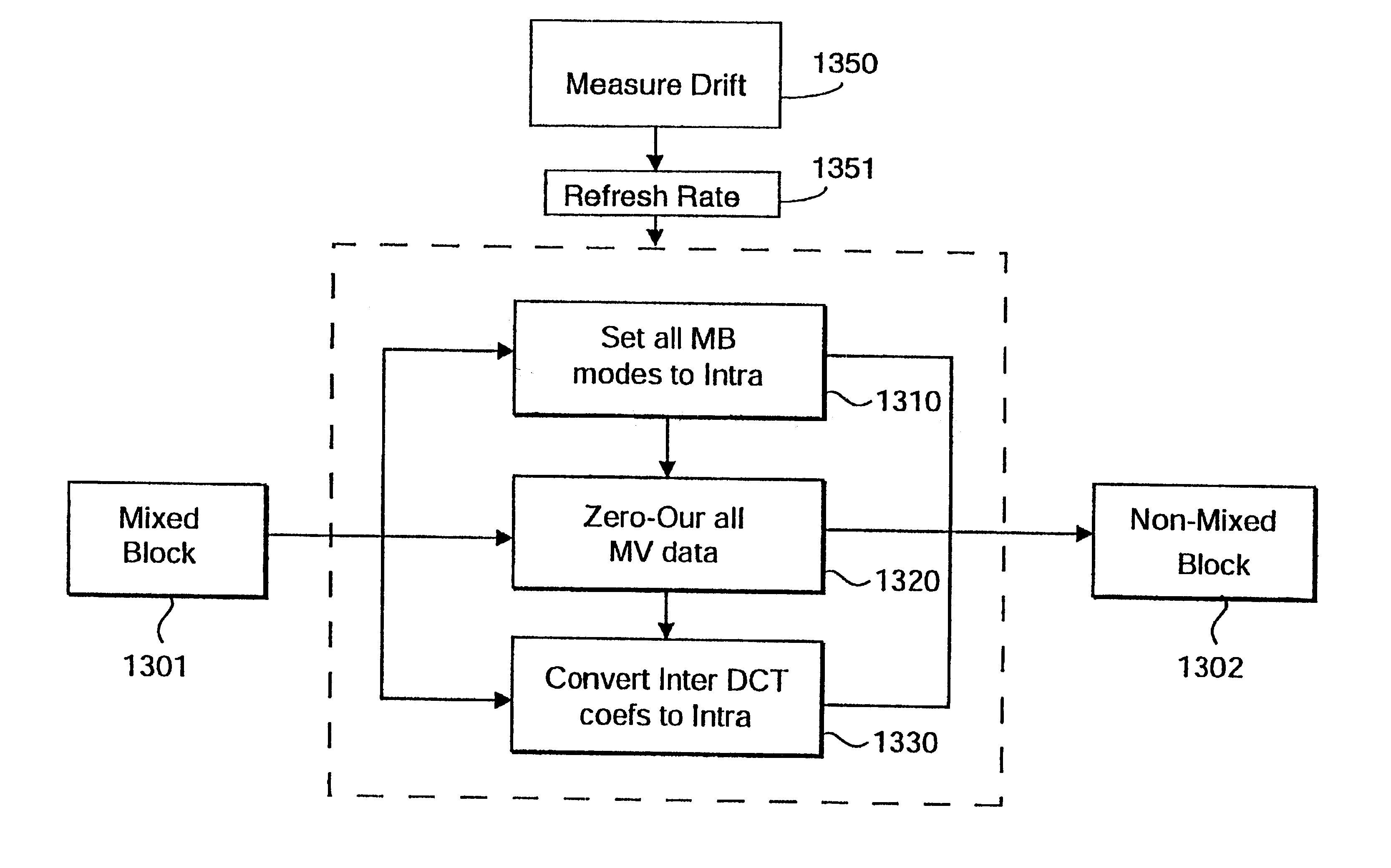
[0088]In the group of blocks processor as shown in FIG. 14A, the MB modes of the group of blocks 1301 are modified to be inter-mode by the mode mapping 1310. Therefore, the MV data for the intra-blocks are reset to zero by the motion vector processing, and the DCT coefficients corresponding to intra-blocks are also reset to zero by the DCT processing 1330. In this way, such sub-blocks that have been converted are replicated with data from the corresponding block in the reference frame.

second embodiment

[0089]In the group of blocks processor as shown in FIG. 14B, the MB modes of the groups of mixed block are modified to be to inter-mode by the mapping 1310. However, in contrast to the first preferred embodiment, the MV data for intra-MB's are predicted. The prediction is based on the data in neighboring blocks, which can include both texture and motion data. Based on this predicted motion vector, a new residual for the modified block is calculated. The final step 1320 resets the inter-DCT coefficients to intra-DCT coefficients.

third embodiment

[0090]In a third embodiment shown in FIG. 14C, the MB modes of the grouped of blocks are modified 1310 to intra-mode. In this case, there is no motion information associated with the reduced-resolution macroblock, therefore all associated motion vector data are reset 1320 to zero. This is necessary to perform in the transcoder because the motion vectors of neighboring blocks are predicted from the motion of this block. To ensure proper reconstruction in the decoder, the MV data for the group of blocks must be reset to zero in the transcoder. The final step 1330 generates intra-DCT coefficients to replace the inter-DCT coefficients, as above.

[0091]It should be noted that to implement the second and third embodiments described above, a decoding loop that reconstructs to full-resolution can be used. This reconstructed data can be used as a reference to convert the DCT coefficients between intra- and inter-modes, or inter- and intra-modes. However, the use of such a decoding loop is not...


PUM


Abstract

A method compensates for drift in macroblocks of a partially decoded input bitstream. The macroblocks include intra-mode and inter-mode macroblocks, and each macroblock includes DCT coefficients, and at least one motion vector. An estimate of drift is measured in the partially decoded input bitstream. The estimated drift is translated into an intra refresh rate. The modes of inter-mode macroblock are mapped to intra-mode macroblock according to the refresh rate. The DCT coefficients and the motion vector for each changed macroblock are modified in accordance with the mapping for each changed macroblock.

Description

FIELD OF THE INVENTION[0001]This invention relates generally to the field of transcoding bitstreams, and more particularly to reducing drift while transcoding video bitstreams.BACKGROUND OF THE INVENTION[0002]Video compression enables the storing, transmitting, and processing of visual information with fewer storage, network, and processor resources. The most widely used video compression standards include MPEG-1 for storage and retrieval of moving pictures, MPEG-2 for digital television, and H.263 for video conferencing, see ISO / IEC 11172-2:1993, “Information Technology—Coding of Moving Pictures and Associated Audio for Digital Storage Media up to about 1.5 Mbit / s—Part 2: Video,” D. LeGall, “MPEG: A Video Compression Standard for Multimedia Applications,” Communications of the ACM, Vol. 34, No. 4, pp. 46-58, 1991, ISO / IEC 13818-2:1996, “Information Technology—Generic Coding of Moving Pictures and Associated Audio Information—Part 2: Video,” 1994, ITU-T SG XV, DRAFT H.263, “Video Co...

Claims


Application Information

Patent Timeline
Patent Type & Authority Patents(United States)
IPC IPC(8): H04N7/12H04N7/32H03M7/30H04N7/26H04N7/36H04N7/46H04N7/50
CPCH04N19/51H04N19/61H04N19/59H04N19/40H04N19/107
Inventor VETRO, ANTHONYSUN, HUIFANGYIN, PENGLIU, BEDEPOON, TOMMY C.
Owner MITSUBISHI ELECTRIC RES LAB INC
Why Eureka
Try Eureka