Embedding data in material

a technology of embedded data and material, applied in the field of embedded data in material, can solve the problems of difficult removal of embedded data from material, easy damage of embedded data, fragile watermarks,

Inactive Publication Date: 2006-08-08
SONY UK LTD
View PDF18 Cites 17 Cited by
  • Summary
  • Abstract
  • Description
  • Claims
  • Application Information

AI Technical Summary

Benefits of technology

[0019]Thus αi is adapted to each coefficient to which it is applied, allowing it to minimise degradation of the material. That also allows αi to make the embedded data more robust against processing which intentionally or unintentionally damages the embedded data.
[0022]The transform may produce coefficients Ci in a plurality of frequency bands. The transform coefficients forming the set {Cn} {Cn}; may be all in the same band. The transform coefficients forming the set {Cn}i may be in a plurality of bands. Using a set of coefficients {Cn}i in a plurality of bands allows the data Ri to be concealed in the material using material properties in bands other than the band containing the data Ri. In a preferred embodiment, the coefficients are serially ordered and the coefficients Cn are unmodified coefficients preceding coefficient Ci. During removal of the embedded data such ordering allows the coefficients to be used to calculate ∀i for a subsequent coefficient Ci.

Problems solved by technology

Watermarks may be “robust” in that they are difficult to remove from the material.
Watermarks may be “fragile” in that they are easily damaged by processing which is useful to detect attempts to remove the mark or process the material.
Those properties may be incompatible.
However, embedding a watermark in the material in such a way as to make difficult unauthorised removal may also have the consequence that the watermark is difficult to remove by an authorised person.

Method used


Image

  • Embedding data in material
  • Embedding data in material
  • Embedding data in material

Examples


first example

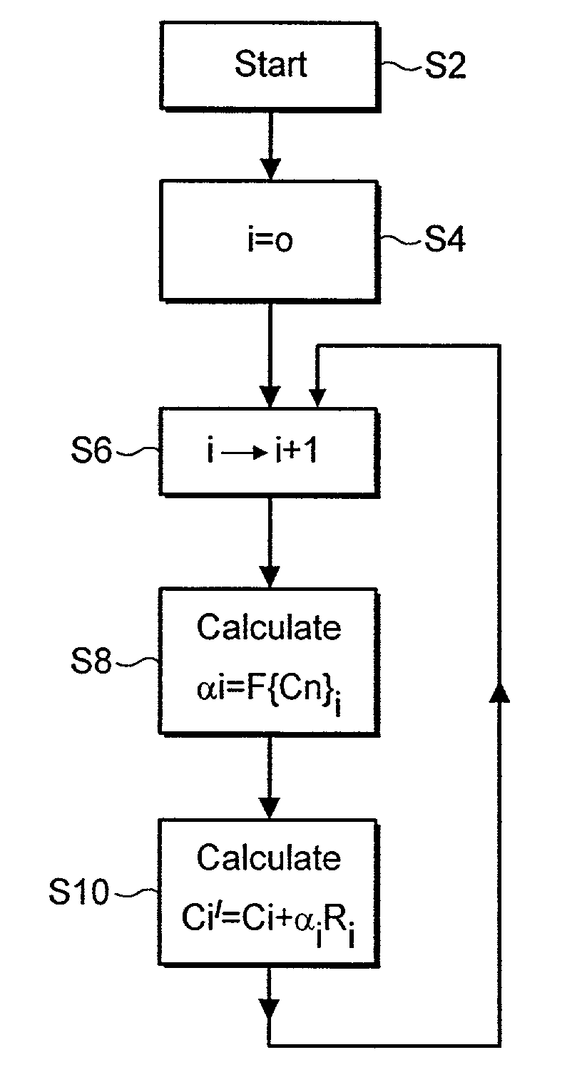
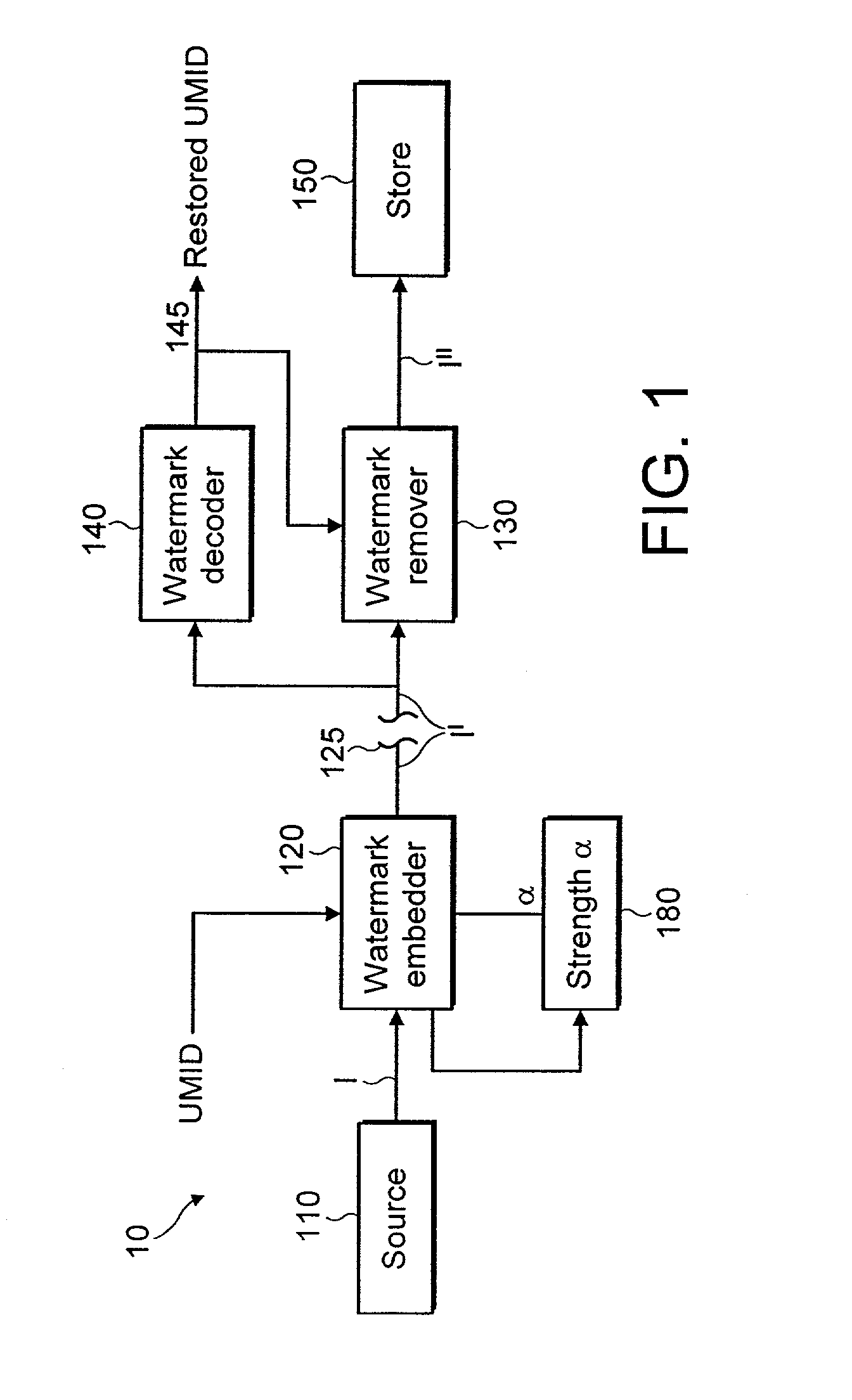
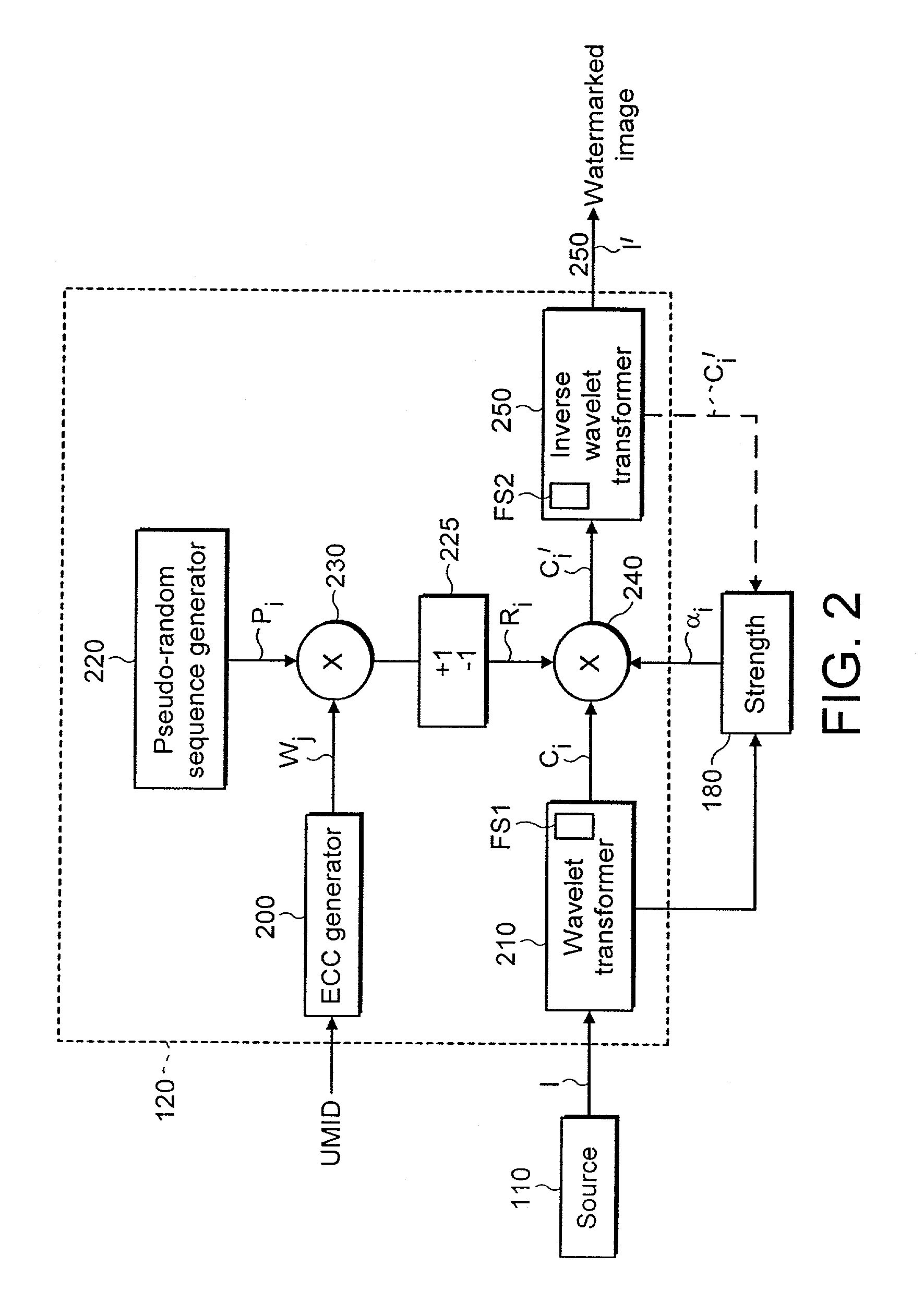
[0155]Referring to FIG. 10, the source 110 produces a spatial domain image I. An embedder 120 receives a UMID from a generator 115 and embeds the UMID as the watermark in wavelet coefficients Ci of a wavelet transform (T) of the image according to

Ci′=Ci+α.Ri

[0156]where Ci is the i′″ original image coefficient. Ci is the ith modified coefficient, Ri is ith bit of watermark data and α is a scaling factor. As described hereinafter Ri may be a bit of a pseudo random symbol sequence modulated by the UMID data Wi.

[0157]The remover 130 removes the watermark to produce restored coefficients Ci″ according to

Ci″=Ci′−α.Ri

[0158]A comparator 125 compares the restored coefficients Ci″ with the original coefficients Ci to determine any differences and the locations thereof. The differences and locations i are stored in the database D as correction data together with the UMID generated by generator 115.

[0159]The coefficients Ci′ produced by the embedder 120 are inverse transformed (T−1) and appli...

second example

[0163]The second example is identical to the first except that a channel emulator 121 is provided between the embedder 120 and remover 130. The emulator applies, to the output of the embedder, a channel emulator function emulating the effect of channel C on the output of the embedder.

[0164]The channel emulation 121 emulates the channel C. Thus errors introduced by the channel C can be detected and corrections stored in the database D.

[0165]This is useful especially if the channel C is lossy.

third example

[0166]This modifies the first or second example in that ∀ is not fixed. The embedder 120 is shown in FIG. 11 and the remover 130, 127 is shown in FIG. 12.

[0167]FIG. 11 is identical to FIG. 2 described above except that it has a connection supplying the wavelet coefficients Ci to the comparator 125 of FIG. 10. Likewise, FIG. 12 is identical to FIG. 6 above except it has a connection supplying the restored coefficients to the comparator 125 of FIG. 10. Thus no further description is needed of FIGS. 11 and 12.

Modifications

[0168]Whilst the aspect of the invention described with reference to FIGS. 10 to 12 embeds and removes watermarks as described with reference to FIGS. 1 to 9, other watermark embedding and removal techniques may be used.

Wavelets

[0169]Wavelets are well known and are described in for example “A Really Friendly Guide to Wavelets” by C Valens, 1999 and available at http: / / perso.wanadoo.fr / polyvalens / clemens / wavelets / wavelets.html.

[0170]Valens shows that the discrete wavel...


PUM


Abstract

A method of embedding data in material comprises the steps of:embedding data in original material to produce data embedded material;removing the watermark from the data embedded material to produce recovered material;comparing the original and recovered material to determine the differences and locations of differences therebetween; andstoring the said locations and corrections which correct the said differences.A method of removing the data embedded in the material, comprises the steps of:removing the data from the material to produce recovered material;deriving the said corrections and locations from the said store; andusing the corrections to correct the recovered material at the said locations.A method of embedding data in material, preferably comprises the steps of:producing transform coefficients Ci representing a spatial frequency transform of the material, andcombining the coefficients Ci with the data bits Ri to produce a modified coefficient Ci′ whereCi′=Ci+αiRi the method further comprising determining αi for each unmodified coefficient Ci as a function F{Cn}i of a predetermined set {Cn}i of transform coefficients Cn which set excludes the coefficient Ci.

Description

BACKGROUND OF THE INVENTION[0001]1. Field of the Invention[0002]The present invention relates to embedding data in material. Embodiments of the invention relate to watermarking material.[0003]“Material” as used herein means information material represented by information signals which includes at least one or more of image material, audio material and data material. Image material is generic to still and moving images and includes video and other information signals representing images.[0004]2. Description of the Prior Art[0005]Steganography is the embedding of data into material such as video material, audio material and data material in such a way that the data is imperceptible in the material.[0006]Data may be embedded as a watermark in material such as video material, audio material and data material. A watermark may be imperceptible or perceptible in the material.[0007]A watermark may be used for various purposes. It is known to use watermarks for the purpose of protecting the ...

Claims


Application Information

Patent Timeline
Patent Type & Authority Patents(United States)
IPC IPC(8): G06K9/00G06T1/00H04N1/32H04N1/387H04N7/08H04N7/081
CPCG06T1/0028G06T1/005H04N1/32154H04N1/3217H04N1/32347G06T2201/0052G06T2201/0081G06T2201/0083G06T2201/0203H04N2201/328G06T2201/0202
Inventor PELLY, JASON CHARLES
Owner SONY UK LTD
Why Eureka
Try Eureka