Vaporizing material at a uniform rate

a technology of vaporization rate and vaporization method, which is applied in the direction of electric/magnetic/electromagnetic heating, furnaces without endless cores, coatings, etc., can solve the problems of many hours to achieve equilibrium temperature and stable vapor deposition rate, and the degradation of organic materials used in the manufacture of oled devices is often subject to degradation, so as to minimize the degradation of materials. , the effect of high uniformity

Active Publication Date: 2007-02-01
GLOBAL OLED TECH
View PDF8 Cites 8 Cited by
  • Summary
  • Abstract
  • Description
  • Claims
  • Application Information

AI Technical Summary

Benefits of technology

[0017] The apparatus and method of the present invention provide a self-compensating vaporization system for vaporizing and depositing a material at a stable rate in spite of some variability in feed rate.
[0018] The apparatus and method of the present invention enable continuous deposition of material at high uniformity using conventional material metering mechanisms. The vaporizable material is maintained at a low temperature during feeding, until it is extended to a position very close to the heating element, minimizing degradation of the material due to exposure to elevated temperatures.

Problems solved by technology

The organic materials used in the manufacture of OLED devices are often subject to degradation when maintained at or near the desired rate-dependent vaporization temperature for extended periods.
Exposure of sensitive organic materials to high temperatures can cause changes in the structure of the molecules and unwanted changes in material properties.
However, as a result, it can require many hours to achieve an equilibrium temperature and a stable vapor deposition rate when using this conventional approach.
Drawbacks of this conventional process include the loss of some portion of the material before it has reached the temperature exposure threshold, a very low vaporization rate due to the limitation on heater temperature, and limited operation time of the source due to the small quantity of material present in the source.
The low deposition rate and the frequent and time consuming process associated with recharging a source has placed substantial limitations on the throughput of OLED manufacturing facilities.
A severe limitation of prior art flash vaporization systems, where the evaporable material is not in liquid form, is the inability to maintain a steady vaporization rate because even small variations in the delivery rate disturb the vaporization rate.
Because of this rate stability problem, the conventional approach teaches away from flash vaporization systems, even where vaporizable material is continuously metered to a heating element.
However, there is a significant difficulty with flash vaporization techniques.
Lower frequency perturbations in the feed rate, however, can be more serious, leading to thickness non-uniformity of the deposited films in scanning type sources.
This precision level of uniformity would be extremely difficult to achieve using, any of today's known metering technologies for any materials not in liquid form.
Adjusting the material feed rate alone however, provides only limited deposition rate control because there may be a time lag of several seconds between a control signal to the feed motor and the resulting change in deposition rate.
In addition, material feed rate is not a bi-directional control variable.
Material already metered to the heating, element cannot typically be retrieved if the deposition rate rises above the desired control limit.
The influence of temperature change, however, can only be applied over a short time interval.
If the heater temperature is driven too high or too low for an extended period of time there can be a material-starved or material-overload condition at the heating element.
Such a closed loop, multi-variable control method is relatively complex as it requires a relationship to be maintained between the material feed rate and the heating element temperature, and it requires tuning to optimize numerous gain settings and requires sensing of material feed, heating element temperature, and vapor deposition rate.

Method used


Image

  • Vaporizing material at a uniform rate
  • Vaporizing material at a uniform rate
  • Vaporizing material at a uniform rate

Examples


Embodiment Construction

[0025] For the description of the present invention that follows, a number of terms must be defined. A “uniform rate” for vapor deposition on a surface would yield a target layer thickness that is uniform to within at least + / −4%, preferably within + / −2%. A “uniform volume” of vaporized material would be provided when the uniform rate is maintained within this tolerance range. A constant heat flux, or constant (DC) current applied to provide a constant heat flux, would vary from an average value by not more than + / −4%, preferably, not by more than 2%. “Low pressure conditions” are defined as having at least some form of vacuum, that is, less than atmospheric pressure conditions.

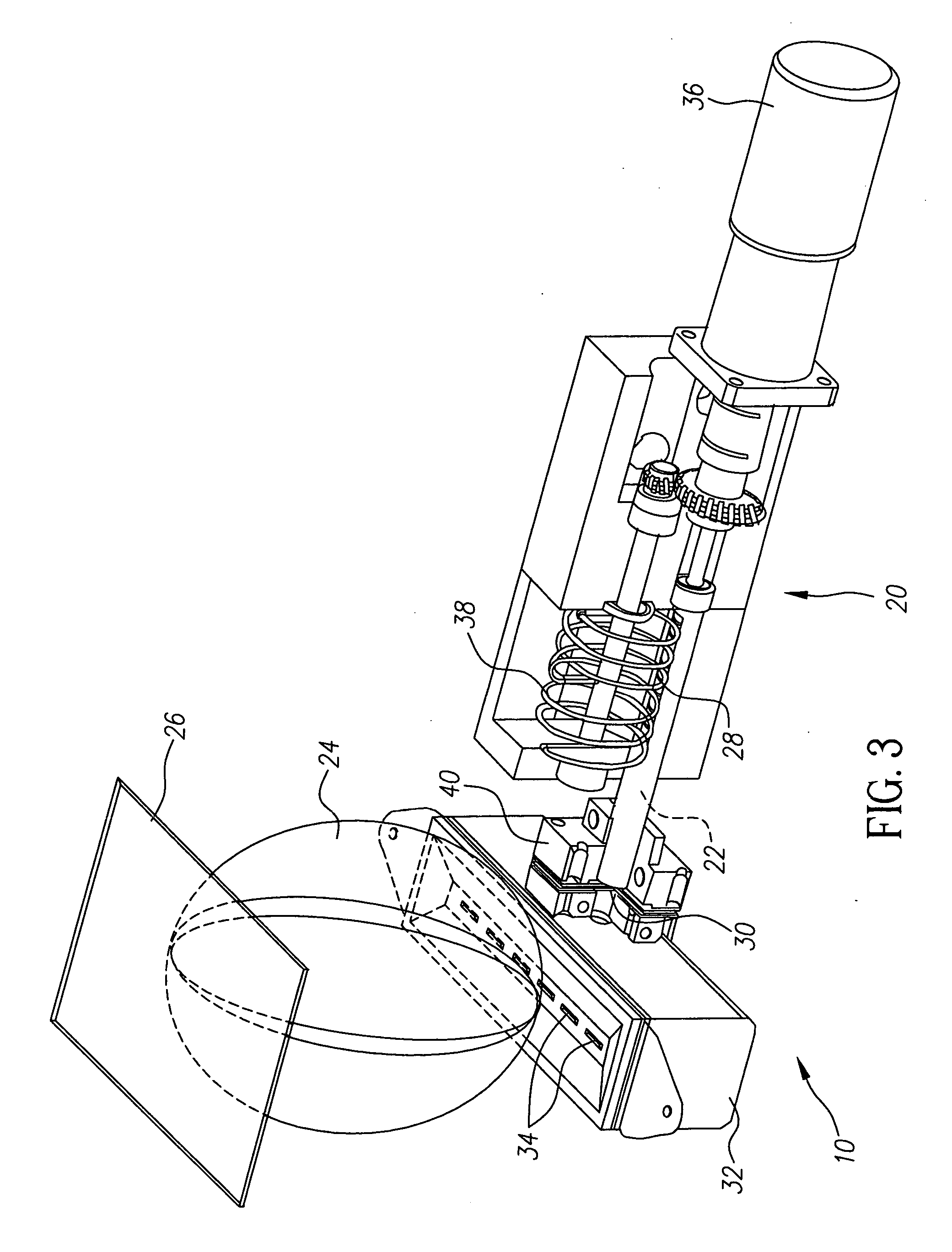
[0026] Referring to FIGS. 3 and 4, there are shown perspective cross-sectional views of material feeding and vaporization components in a vapor deposition apparatus 10 according to one embodiment of the present invention. Feeding apparatus 20 utilizes an auger screw 28 to urge vaporizable material 22 forward...


PUM

PropertyMeasurementUnit
temperatureaaaaaaaaaa
vaporization temperatureaaaaaaaaaa

Abstract

A method of vaporizing material at a uniform rate for forming a layer on a substrate includes feeding a column of vaporizable material from a temperature controlled region maintained below the vaporizable material's effective vaporization temperature to a source of vaporization energy, wherein the volume of the column can vary during vaporization; and providing a source of vaporization energy delivering a constant heat flux to the surface of the column so that a uniform volume per unit time of the vaporizable material is vaporized to form the layer on the substrate, irrespective of the feeding rate.

Description

FIELD OF THE INVENTION [0001] The present invention relates to methods and apparatus for vaporizing material in a chamber at a uniform rate when the feed rate at which the material is supplied may vary. BACKGROUND OF THE INVENTION [0002] Physical vapor deposition in a vacuum environment is the principal means of depositing thin films of material, such as the thin organic material films used in small molecule organic light-emitting diode (OLED) devices. Physical vapor deposition methods are well known, for example in U.S. Pat. No. 2,447,789 to Barr and in and in EP 0 982 411 Tanabe et al. The organic materials used in the manufacture of OLED devices are often subject to degradation when maintained at or near the desired rate-dependent vaporization temperature for extended periods. Exposure of sensitive organic materials to high temperatures can cause changes in the structure of the molecules and unwanted changes in material properties. [0003] Sources is accomplished by placing a quan...

Claims


Application Information

Patent Timeline
Patent Type & Authority Applications(United States)
IPC IPC(8): C23C16/00H05B6/24H05B3/00H05B6/02
CPCC23C14/246C23C14/12C23C14/542C23C14/548
Inventor LONG, MICHAELKOPPE, BRUCE E.
Owner GLOBAL OLED TECH
Why Eureka
Try Eureka