
Automatic machinery fault diagnostic method and apparatus

a technology of automatic machinery and fault diagnosis, applied in the field of automatic fault diagnosis procedure for machines, can solve the problems of not being able to predict the future development of this fault, the capacity and the amount of data to be analysed reaching the limit of the computer executing the algorithm of the expert system. , the risk of misinterpretation of results, the effect of reducing the time it takes the auto-diagnostic software to process stored data

Inactive Publication Date: 2006-08-08
GP ROVSING DYNAMICS APS
View PDF8 Cites 58 Cited by
  • Summary
  • Abstract
  • Description
  • Claims
  • Application Information

AI Technical Summary

Benefits of technology

[0008]By calculating parameters representing the strength of a number of physical symptoms, and then combining these parameters to give a value of total fault symptom strength, it is possible to automatically evaluate the state of a component with regard to each of a number of possible faults. This approach works much better than expert systems or approaches using automatic training of a system using training data because the method according to the invention is able to focus on the specific features of the dataset indicative of each fault.
[0010]The step of combining the symptom values may include calculating the sum of the symptom values raised to the power of a predetermined constant and taking the predetermined constant root of the sum. In this way, it is avoided that a single outlier value has too great an effect on the final calculation, while still combining all the symptom values.
[0012]The signature dataset may be a database. The method may include automatically taking measurements of the component when predetermined conditions occur, such as at regular intervals, and testing whether the new measurements represent a change on the reduced data stored in the signature database. If there is no change, preferably simply this fact is recorded, alternatively the data may simply be abandoned. This approach avoids adding unnecessary data to the signature database thereby reducing the amount of data required to be stored.
[0028]In machines used in power plants, there are often several hundred critical components, and since several machines are in use simultaneously, and these machines further have to be keep under surveillance simultaneously, the amount of data from the involved measuring transducers increases very quickly. Embodiments of the invention achieves a reduction of the observed data.
[0031]The analysis may be performed on the heavily reduced data sets being stored in the server database. As a result, the time it takes the auto-diagnostic software to process the stored data is reduced considerably. Furthermore, since the auto-diagnostic software in addition works with signatures specific to particular kinds of faults in particular components, the risk of misinterpretations of the results and, hence, the untimely issue of false alarms are also reduced considerably.

Problems solved by technology

As regards the use of expert systems, the results from such systems may merely indicate the association of a symptom with the likelihood of a potential fault, but does not predict the future development of this fault.
Furthermore, expert systems are sensitive to boundary conditions of the collected data and knowledge, and may even indicate faults, which would possibly not occur in practice.
In addition, such a method, when monitoring the many machine components, soon arrives at a point where the amount of data to be analysed reach the limit of the capacity of the computer executing the algorithms of the expert system.
Expert systems and other types of automatic fault detection systems also require training, and the difficulty of training an expert system for the many different types of fault and indicators thereof maybe prohibitive.

Method used


Image

  • Automatic machinery fault diagnostic method and apparatus
  • Automatic machinery fault diagnostic method and apparatus
  • Automatic machinery fault diagnostic method and apparatus

Examples


example

[0082]The principles of configuration and execution of auto diagnosis will now be illustrated for a typical machine component; a rotor. In the following, one practical example of configuration and operation of the Fault Diagnostic System will be explained. The example concerns a rotor supported in journal bearing. The system's Machine Fault Library includes three general classes of rotors characterised by mechanical configuration and applicable instrumentation; one of these, the rotor with journal bearings, is selected.

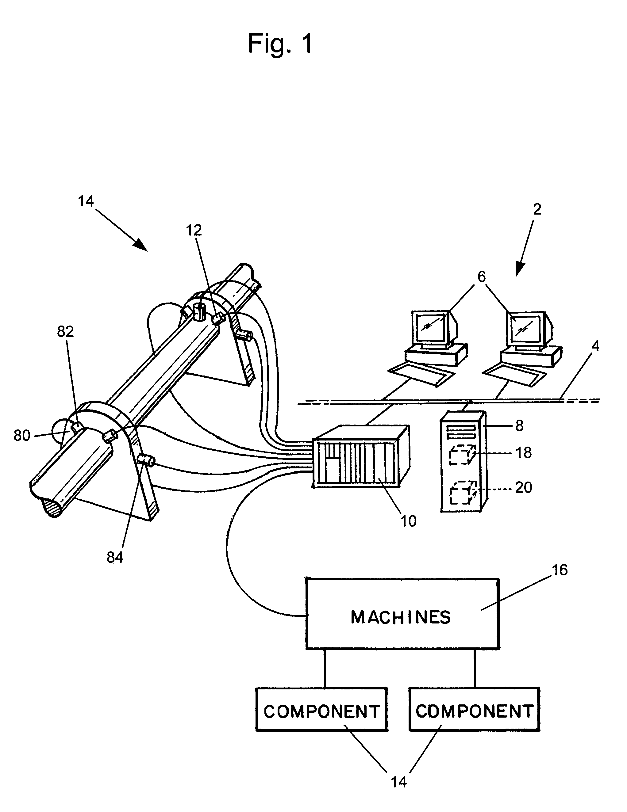
[0083]FIG. 1 shows a rotor 14 as part of a generic machine supported by two journal bearings 80. At each bearing 80, two displacement probes 82 and one accelerometer 84 are mounted. The signals from the displacement probes 82 and the accelerometer 84 are fed to a signal processing unit 10 for calculating the particular signatures, that subsequently are sent to the central server 8 and saved in the database 44.

[0084]The potential faults for the rotor are unbalance, mis...


PUM


Abstract

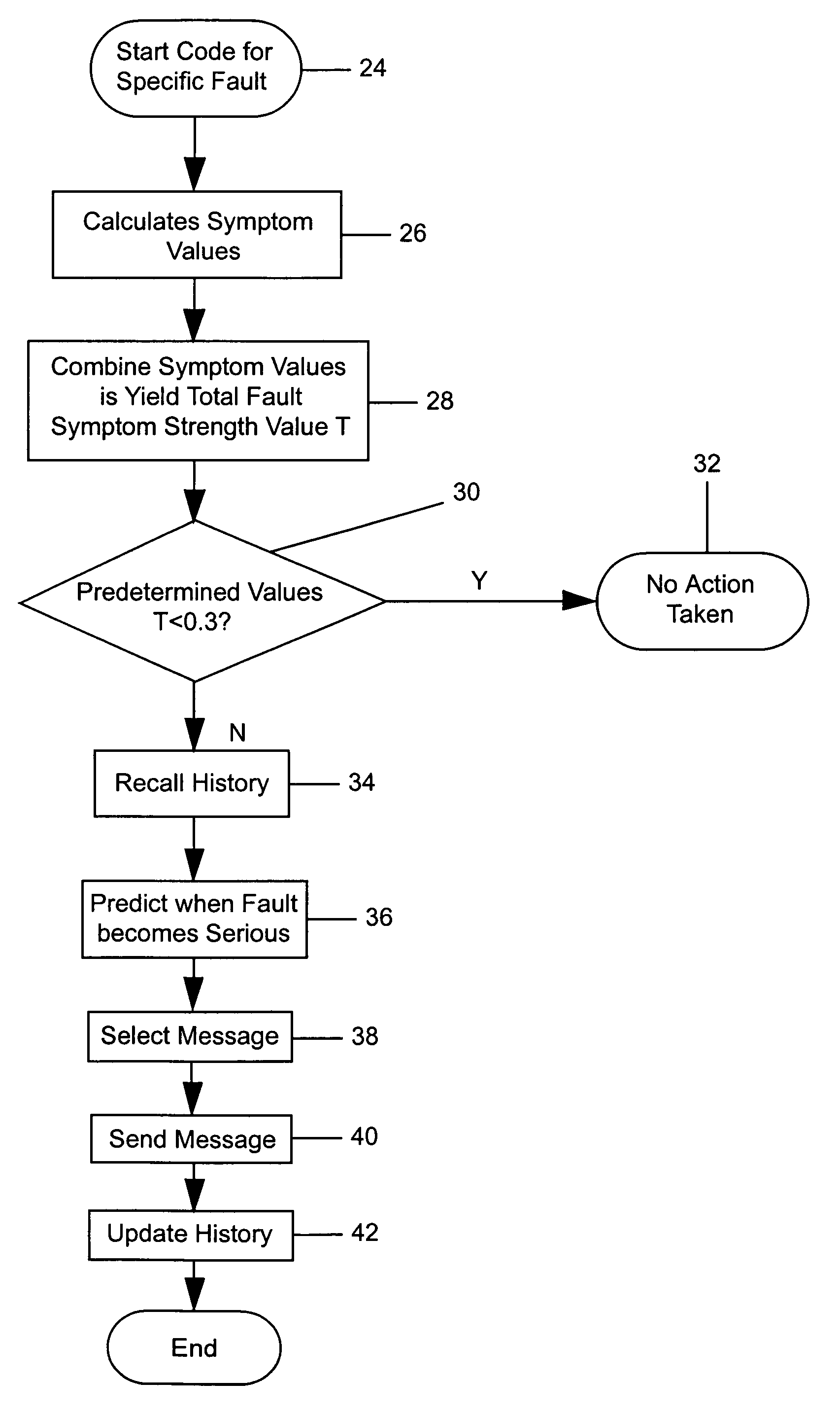
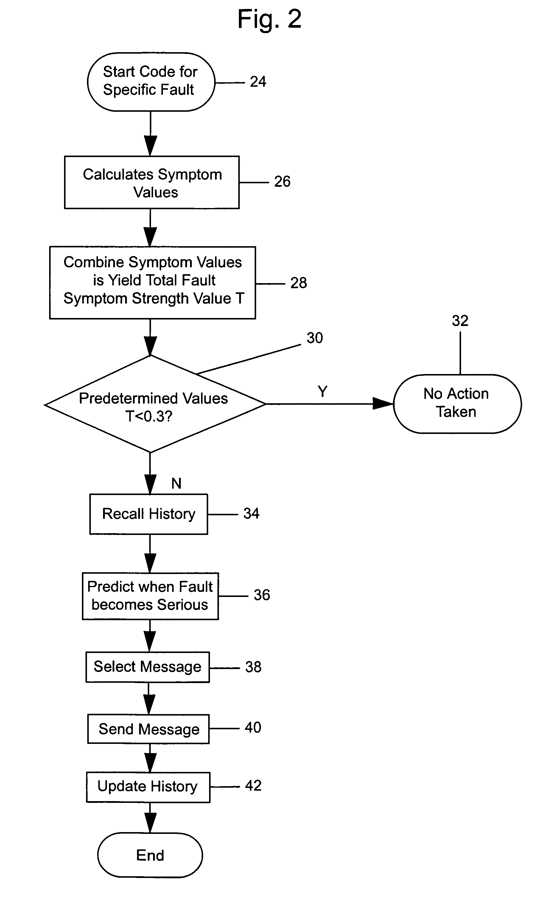
The invention relates to an automatic fault diagnostic procedure for machines, such as steam, gas and hydro-turbines, generators, pumps, electrical motors, etc. For each of a plurality of components, for each of a number of possible faults, a total fault symptom strength value is calculated from measured data. If the value is above a predetermined value, the fault symptom strength is plotted and fitted to a trend line to determine an estimate of when the fault symptom strength will exceed a predetermined value. Output messages are then selected based on the fit.

Description

FIELD OF THE INVENTION[0001]The invention relates to an automatic fault diagnostic procedure for machines, such as steam, gas and hydro-turbines, generators, pumps, electrical motors, etc.BACKGROUND OF THE MENTION[0002]Various attempts to monitor the health and make fault diagnoses of machines have been attempted. Conventionally, this is done by human experts after abnormal behaviour, such as increased vibration level, has been observed. The experts may in cases be supported by expert systems.[0003]The fault diagnosis may include analysing vibration and process data from critical machines to determine whether the specific machine components show a tendency of imbalance, misalignment, cracks, wear or other faults.[0004]As regards the use of expert systems, the results from such systems may merely indicate the association of a symptom with the likelihood of a potential fault, but does not predict the future development of this fault. Furthermore, expert systems are sensitive to bounda...

Claims


Application Information

Patent Timeline
Patent Type & Authority Patents(United States)
IPC IPC(8): G06F11/30G01D3/08
CPCG01M13/045G01D3/08
Inventor RASMUSSEN, SOREN A.DOSSING, OLE
Owner GP ROVSING DYNAMICS APS
Learn More