Computer management system

a computer management system and computer technology, applied in the field of management systems, can solve problems such as the increase of the load of system operators and the cost of such an increas

Inactive Publication Date: 2006-08-08
HITACHI LTD
View PDF46 Cites 27 Cited by
  • Summary
  • Abstract
  • Description
  • Claims
  • Application Information

AI Technical Summary

Benefits of technology

[0008]The system management which is conducted by the manager of the remote management computer through the agent of the computer to be managed as it is in the LAN-connected system is suitable for the steady system management where the computer to be managed operates normally. On the other hand, when the system management is attained by connecting the modem and the line directly to the fault monitoring extended board, it is suitable for the system management in which a critical fault occurs in the computer to be managed and the agent cannot operate. Thus it is a system management method which is effective in different and exclusive situations. In light of the above, it is an object of the present invention to provide means to realize the remote system management by the above two methods by one remote management computer and one modem. Thus, the redundant remote management computer, line and modem which causes a problem in the operation is eliminated.

Problems solved by technology

In such a CSS system, as a scale thereof expands, the number of computers functioning as the clients and servers extends to several hundreds to several thousands and when the network manages and operates the respective computers manually by the system operators, the loads of the system operators and the cost therefor increase, which causes a problem.
This may cause a problem in the operation.

Method used


Image

  • Computer management system
  • Computer management system
  • Computer management system

Examples


Embodiment Construction

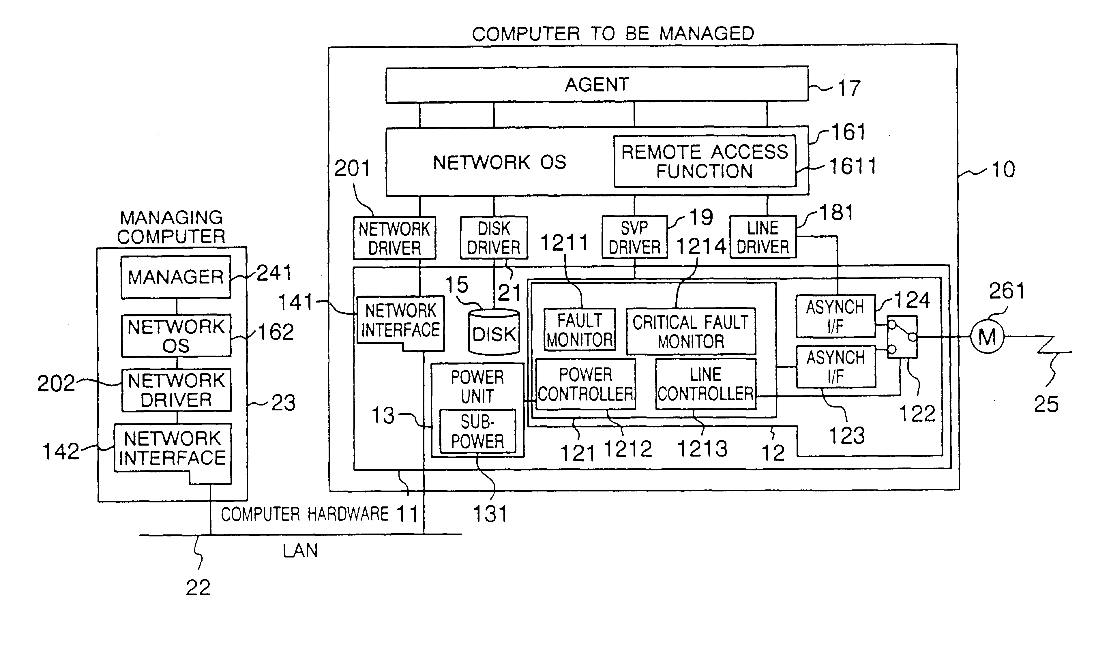
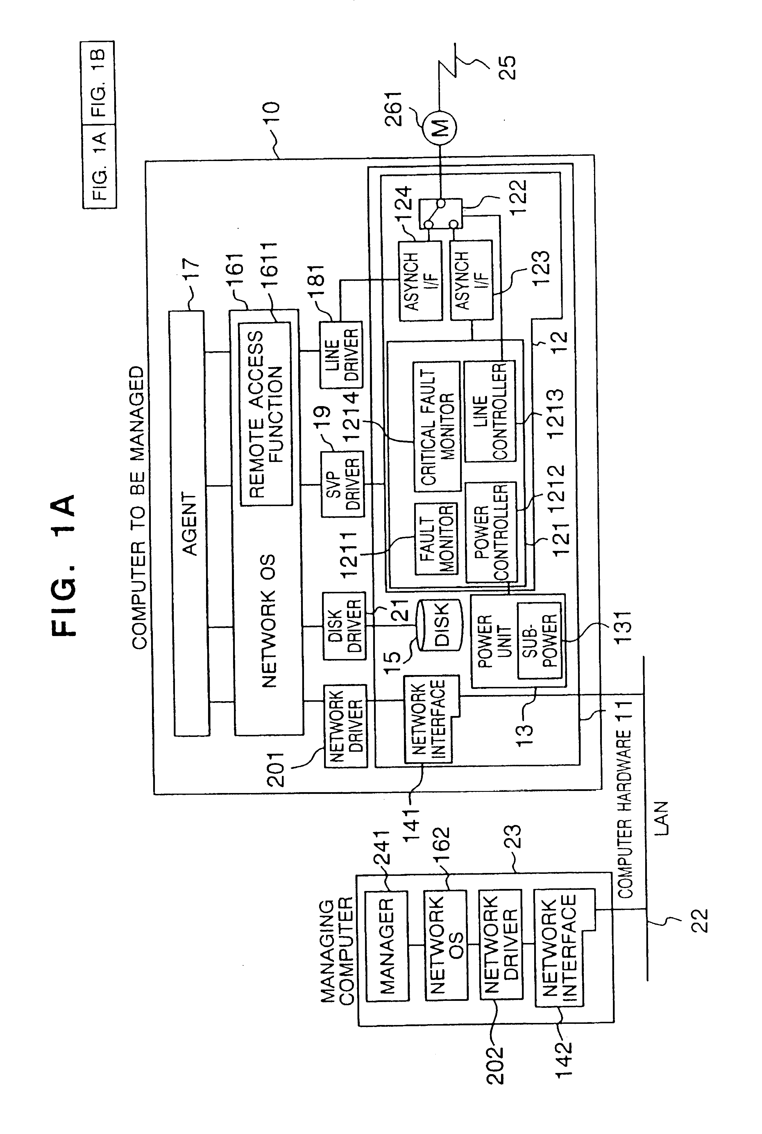
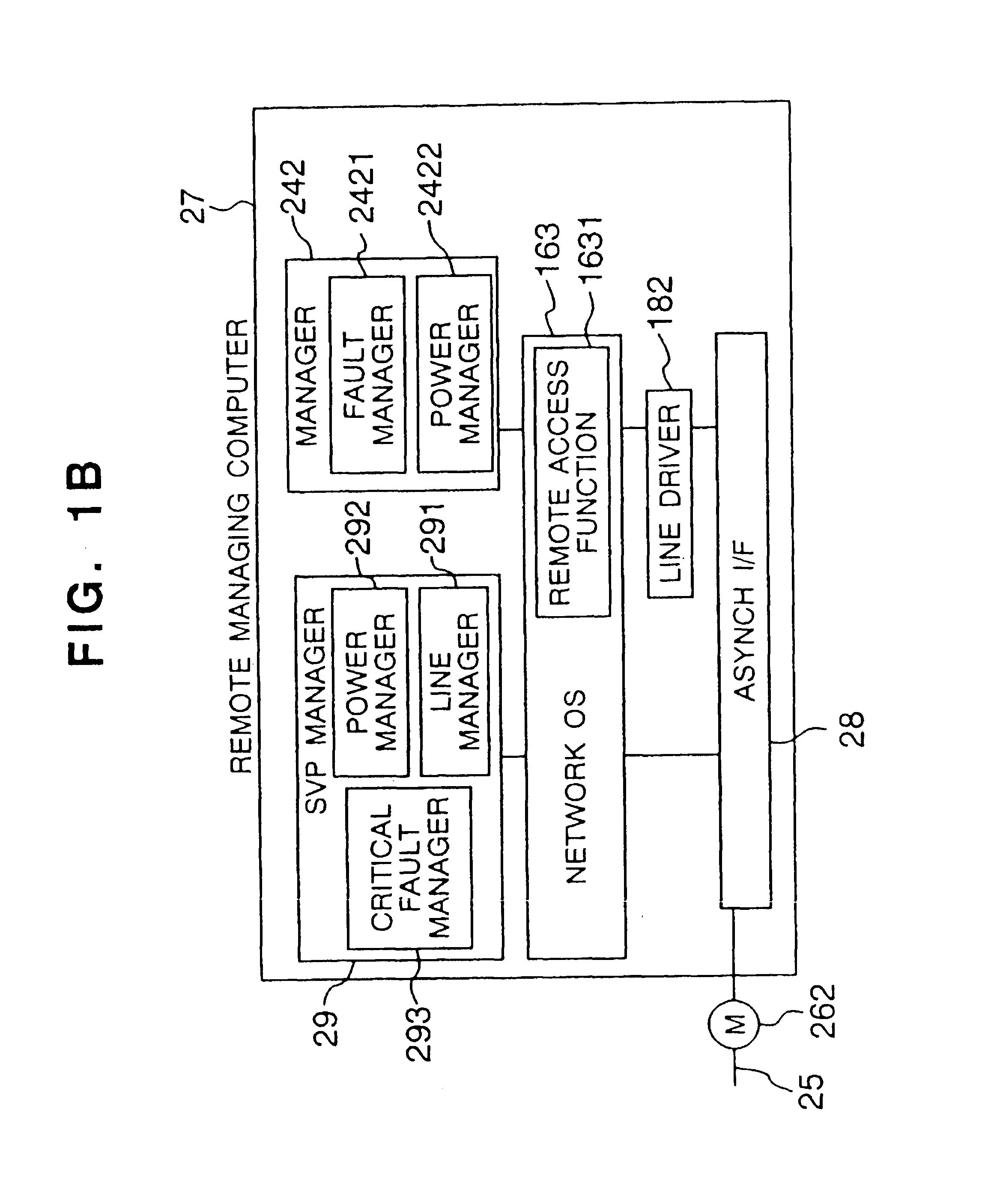
[0041]FIGS. 1A and 1B show in a group a block diagram of one embodiment of the present invention. A configuration thereof is now explained.

[0042]Numeral 10 denotes a computer to be managed, numeral 11 denotes hardware of the computer to be managed, numeral 12 denotes an SVP board, numeral 121 denotes an SVP controller which is firmware for controlling by a processor of the SVP, numeral 122 denotes a switching circuit of an asynchronous interface, numeral 123 denotes an asynchronous interface (hereinafter referred to as an asynchronous I / F) connected to the processor of the SVP board, numeral 124 denotes an asynchronous I / F accessible by the computer 10 to be managed, numeral 13 denotes a power unit, numeral 131 denotes a sub-power supply for continuously supplying a power to the SVP board, numerals 141 and 142 denote LAN adapters, numeral 15 denotes a disk drive, numerals 161, 162 and 163 denote network OSs for conducting communication by the computers, numerals 1611 and 1631 denote...


PUM


Abstract

A computer management system attains, through one line, the uniform and steady system management through an agent such as monitoring of fault and power control in a computer connected by LAN as well as a public line, and system management for an off-state of the computer or abnormal operation state of the computer such as remote power control and notice and diagnosis of critical fault by the direct connection with a service processor through the line. The system includes an agent connected to a computer to be managed for executing instructions on the computer to be managed, a service processor board having a processor independent from the computer to be managed for monitoring fault in the computer to be managed and controlling power of the computer to be managed, a manager for executing instructions on a management computer and conducting controls such as fault monitoring and power control through the agent over a network including a public line, and a service processor manager directly connected to the service processor for conducting remote power-on and receiving and diagnosing critical fault. The service processor and the service processor manager are provided with switching circuits for switching an asynchronous interface for remotely connecting to the computer to be managed and an asynchronous interface for directly connecting to a local processor of the service processor.

Description

CROSS-REFERENCE TO RELATED APPLICATION[0001]This application is a continuation of application Ser. No. 09 / 475,057 filed Dec. 30, 1999, now U.S. Pat. No. 6,199,180 which in turn is a continuation of application Ser. No. 09 / 144,174 flied Aug. 31, 1998 (now U.S. Pat. No. 6,044,476), which in turn is a continuation of application Ser. No. 08 / 655,482 filed May 30, 1996 (now U.S. Pat. No. 5,815,652).BACKGROUND OF THE INVENTION[0002]The present invention relates to a management system (hereinafter referred to as a manager) for a computer system and more particularly to a manager for monitoring and controlling fault and performance of a plurality of computers on a network through the network in a client server system (hereinafter referred to as a CSS) in which a plurality of computers are connected by the network such as a local area network (hereinafter referred to as a LAN) or a public line.[0003]As the performance of a personal computer and a workstation is enhanced, it has become popula...

Claims


Application Information

Patent Timeline
Patent Type & Authority Patents(United States)
IPC IPC(8): G06F11/00G06F11/07G06F11/22G06F11/273G06F11/30G06F11/32G06F11/34
CPCG06F11/0709G06F11/0784G06F11/22G06F11/2294G06F11/3006G06F11/3055G06F11/3072G06F11/0748H04L43/0817G06F11/079G06F11/0793G06F11/2205G06F11/327G06F11/3495H04L43/0811
Inventor OTE, ICHIROFURUKAWA, HIROSHIWASHIMI, HIROAKIKOBAYASHI, YUICHISAKURAI, SHIGERUKARASAKI, TEIJIMIYAGAWA, YUJIMURAI, MASAMITOBITA, TSUNEHIRO
Owner HITACHI LTD
Why Eureka
Try Eureka