Error response test system and method using test mask variable

a test system and mask variable technology, applied in error detection/correction, instruments, computing, etc., to achieve the effect of improving performance and increasing functionality

Inactive Publication Date: 2006-08-08
HONEYWELL INT INC
View PDF10 Cites 12 Cited by
  • Summary
  • Abstract
  • Description
  • Claims
  • Application Information

AI Technical Summary

Benefits of technology

[0012]The present invention provides an error response test system and method with increased functionality and improved performance. The error response test system provides the ability to inject errors into the application under test to test the error response of the application under test in an automated and efficient manner.

Problems solved by technology

During testing, the error response system can change the test mask variable to a value that interferes with the results of the built-in test routine, causing it to fail.

Method used


Image

  • Error response test system and method using test mask variable
  • Error response test system and method using test mask variable
  • Error response test system and method using test mask variable

Examples


Embodiment Construction

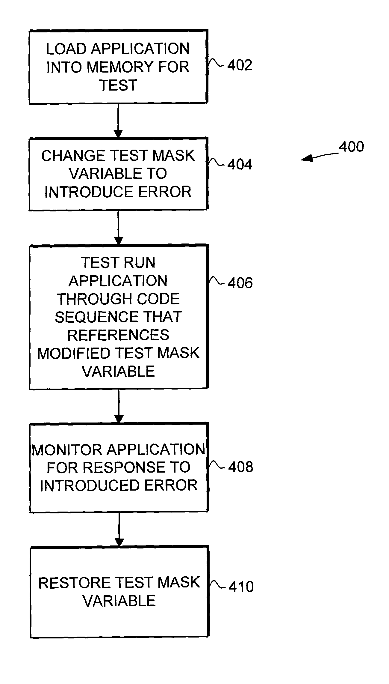
[0023]The present invention provides an error response test system and method with increased functionality and improved performance. The error response test system provides the ability to inject errors into the application under test to test the error response of the application under test in an automated and efficient manner.

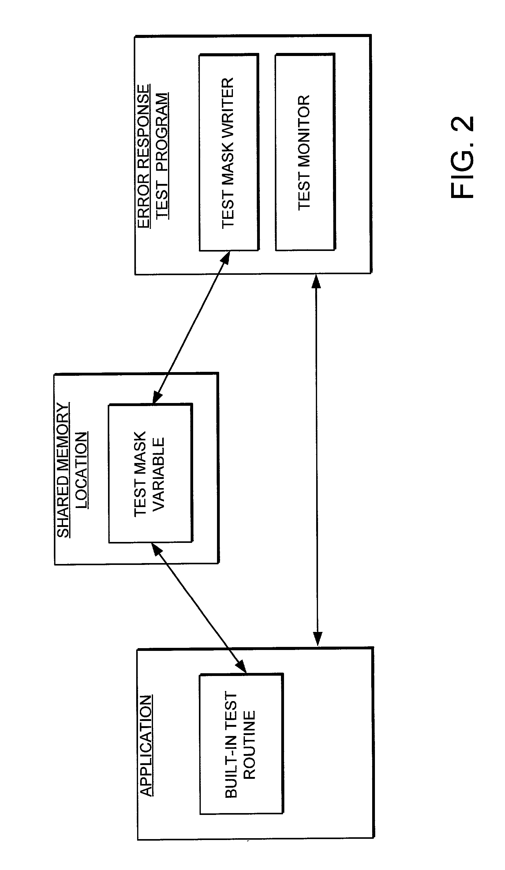
[0024]The error response system injects errors into the application through a test mask variable. The test mask variable is permanently added to the application under test. This has a negligible performance impact on the application, particularly for built-in test routines. During normal operation, the test mask variable is set to allow the application under test to operate normally. During testing, the error response test system can change the test mask variable to introduce an error into the application under test. The error response system can then monitor the application under test to determine whether the application has the correct response to the error.

[...


PUM


Abstract

An error response test system and method with increased functionality and improved performance is provided. The error response test system provides the ability to inject errors into the application under test to test the error response of the application under test in an automated and efficient manner. The error response system injects errors into the application through a test mask variable. The test mask variable is added to the application under test. During normal operation, the test mask variable is set to allow the application under test to operate normally. During testing, the error response test system can change the test mask variable to introduce an error into the application under test. The error response system can then monitor the application under test to determine whether the application has the correct response to the error.

Description

STATEMENT OF GOVERNMENT INTEREST[0001]The U.S. Government has a paid-up license in this invention and the right in limited circumstances to require the patent owner to license to others on reasonable terms as provided for by the terms of Contract No. NAS15-10000 awarded by the National Aeronautics and Space Administration (NASA), Boeing Subcontract No. 940S9001.BACKGROUND OF THE INVENTION[0002]1. Technical Field[0003]This invention generally relates to computer systems, and more specifically relates to testing of computer systems.[0004]2. Background Art[0005]Modern life is becoming more dependent upon computers. Computers have evolved into extremely sophisticated devices, and may be found in many different applications. These applications involve everything from application specific computers found in everyday devices such as automobiles, phones and other electronics, to the general purpose computers found in the form of PDAs, personal computers, servers and mainframes.[0006]As comp...

Claims


Application Information

Patent Timeline
Patent Type & Authority Patents(United States)
IPC IPC(8): G06F11/00G06F11/28G06F11/36
CPCG06F11/3688
Inventor GENDER, THOMAS K.
Owner HONEYWELL INT INC
Why Eureka
Try Eureka