Casing cutter

a cutter and casing technology, applied in the field of tools, can solve the problems of difficulty in interfacing the various tools to the platform or tools needed to effect the cutting and removal, difficulty in customization, and difficulty in achieving the effect of cutting and removal,

Active Publication Date: 2006-08-15
OCEANEERING INTERNATIONAL
View PDF14 Cites 40 Cited by
  • Summary
  • Abstract
  • Description
  • Claims
  • Application Information

AI Technical Summary

Problems solved by technology

Often this is a difficult task.
Although standard, e.g. off-the-shelf type, tools are available, interfacing the various tools to platforms or tools needed to effect the cutting and removal is often difficult and often requires some degree of customization.

Method used


Image

  • Casing cutter
  • Casing cutter
  • Casing cutter

Examples


Embodiment Construction

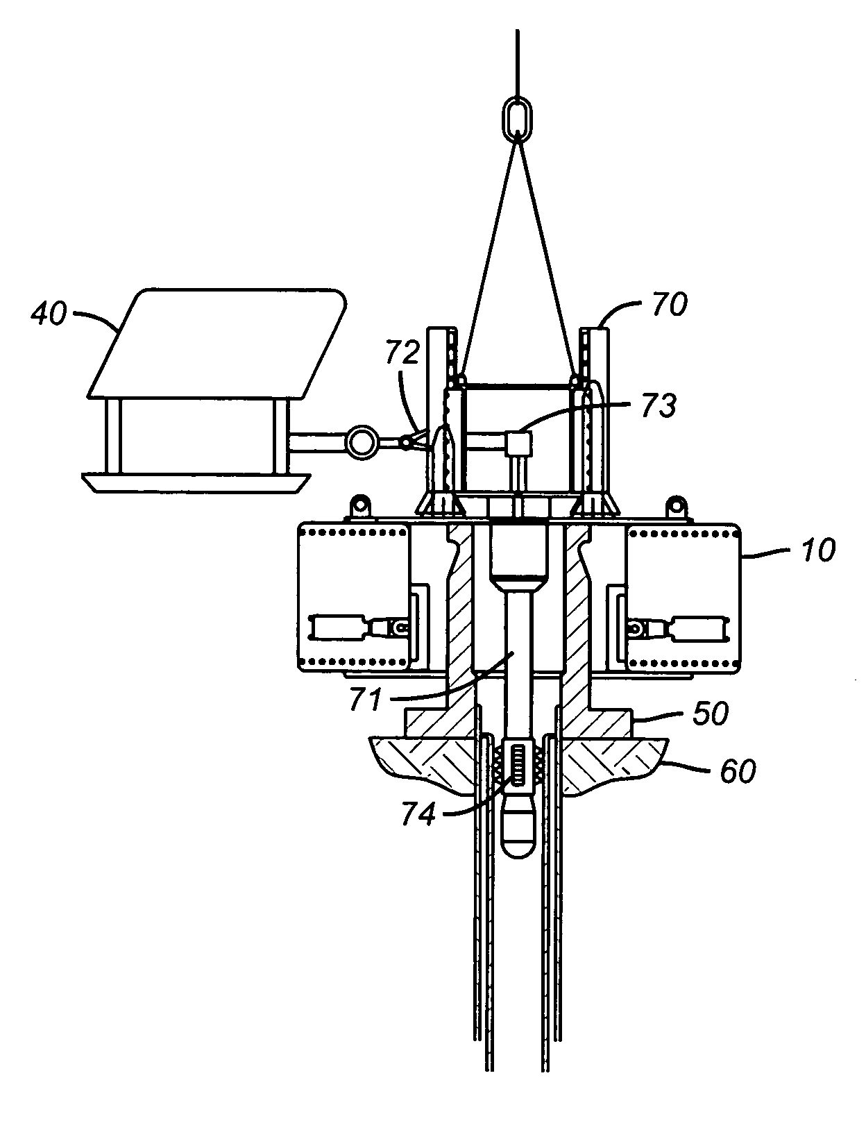
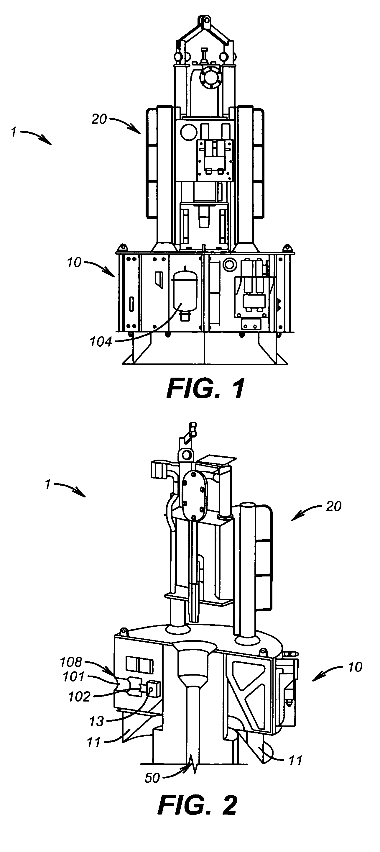
[0011]Referring now to FIGS. 1 and 2, subsea well casing cutting tool 1 is adapted to be deployed from a vessel located at a water's surface (not shown the figures). In an embodiment, subsea well casing cutting tool 1 comprises casing gripper 10 and rotary cutter drive assembly 20.

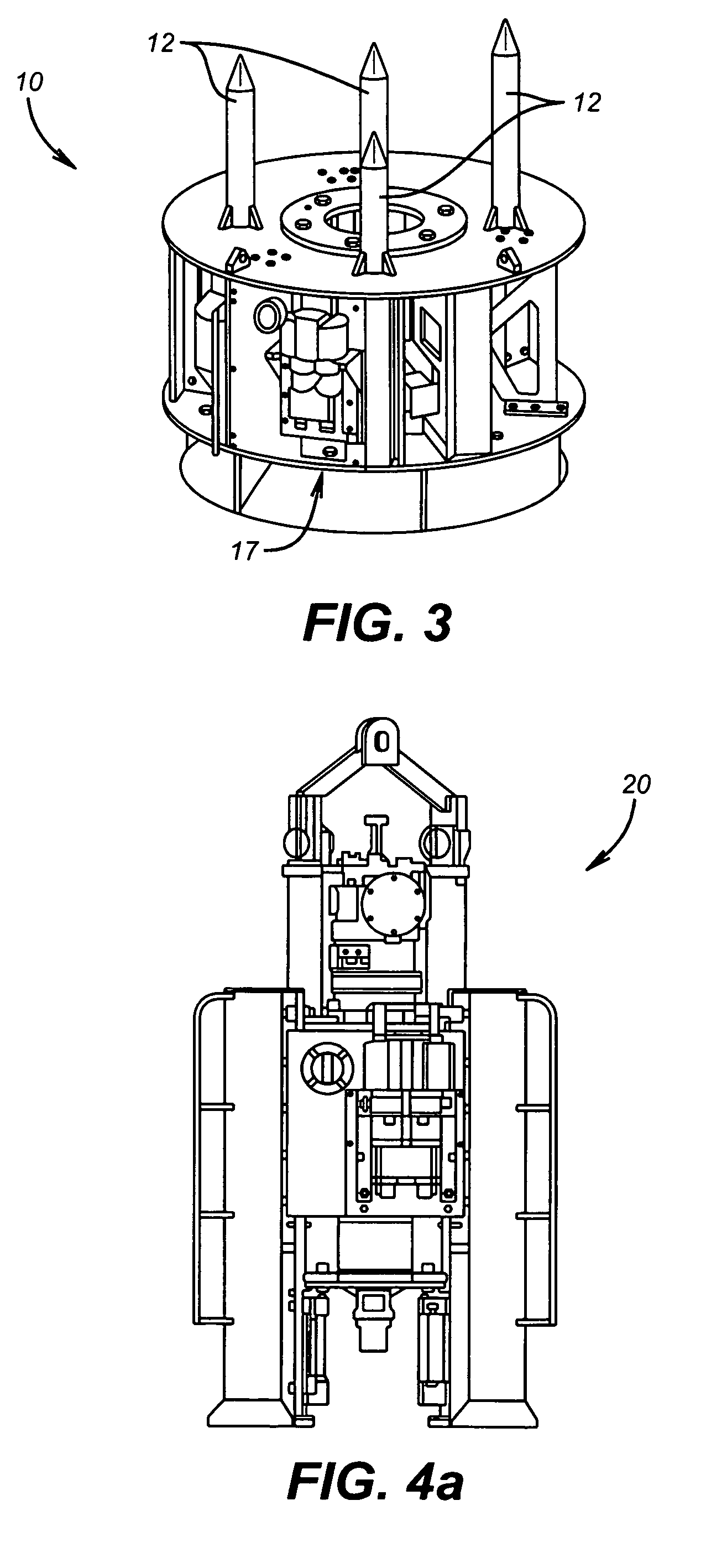
[0012]Referring now additionally to FIGS. 2 and 3, casing gripper 10 comprises one or more casing guides 11 adapted to land casing gripper 10 on casing 50, one or more landing guides 12 (FIG. 3), and one or more clamps 13 adapted to secure casing gripper 10 about casing 50. As used herein, “casing” may be a casing, a tubular, a wellhead, or a similar component.

[0013]Casing guide 11 is adapted to help subsea well casing cutting tool 1 land on a top face of casing 50 and center rotary cutter drive assembly 20 in casing 50. In a preferred embodiment, casing guides 11 further comprise a plurality of hydraulic cylinders 108, each hydraulic cylinder 108 comprising piston 101; a plurality of jaw blocks 102, each ...


PUM


Abstract

A subsea well casing cutting tool for use as part of a well abandonment procedure, the casing cutting tool deployable from a vessel located at a water surface, where in certain embodiments the casing cutting tool comprises a casing gripper; a rotary cutter drive assembly; a rotary cutter; a rotating fluid union that allows high volume water to be fed to the rotating cutting assembly below the drive motor for purposes of extending the cutting blades; and a third party casing hanger removal tool wherein the casing cutting drive assembly forms an interface between the third party rotary casing cutter, an existing subsea casing, and a work class ROV. It is emphasized that this abstract is provided to comply with the rules requiring an abstract which will allow a searcher or other reader to quickly ascertain the subject matter of the technical disclosure. It is submitted with the understanding that it will not be used to interpret or limit the scope of meaning of the claims.

Description

RELATION TO PRIOR APPLICATIONS[0001]This application claims priority through U.S. Provisional Application 60 / 494,518, filed Aug. 12, 2003.FIELD OF INVENTION[0002]The present invention relates generally to the field of tools suitable for use subsea to manipulate casings underwater, e.g. to cut them.BACKGROUND OF THE INVENTION[0003]Casings often need to be cut underwater, in situ. At times, portions of tubulars, e.g. casings or wellheads, need to be removed, such as when a well is abandoned. Often this is a difficult task.[0004]Although standard, e.g. off-the-shelf type, tools are available, interfacing the various tools to platforms or tools needed to effect the cutting and removal is often difficult and often requires some degree of customization.BRIEF DESCRIPTION OF THE DRAWINGS[0005]The various drawings supplied herein are representative of one or more embodiments of the present inventions.[0006]FIG. 1 is a view from a side of an exemplary embodiment showing a casing gripper coupl...

Claims


Application Information

Patent Timeline
Patent Type & Authority Patents(United States)
IPC IPC(8): E21B29/12B23BE21B29/00E21B33/038
CPCE21B29/005
Inventor BARROW, STEVETHORNE, DONALD L.BENSON, DAN THOMASMCCOY, RICH
Owner OCEANEERING INTERNATIONAL
Why Eureka
Try Eureka