

Conveyor system
a conveying system and conveying technology, applied in the field of conveying systems, can solve the problems of increasing the speed of conveying, louder contacting noise, and reducing the contacting noise between the chain and the supporting plate, so as to reduce the contacting noise and prevent hanging, the effect of reducing the contacting nois
- Summary
- Abstract
- Description
- Claims
- Application Information
AI Technical Summary
Benefits of technology
Problems solved by technology
Method used
Image

Examples
first embodiment
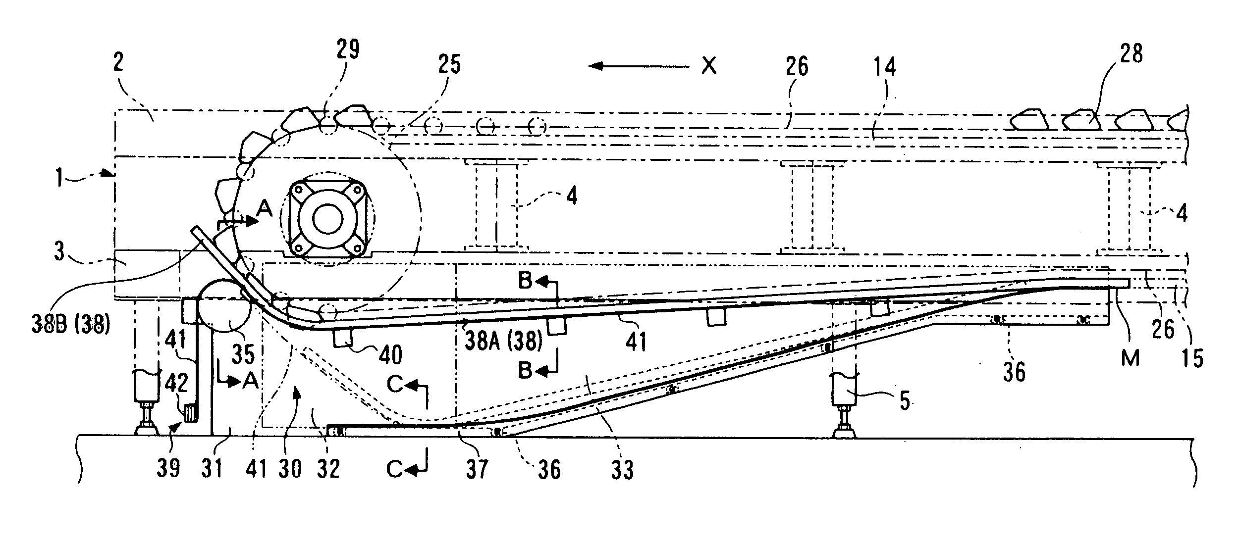
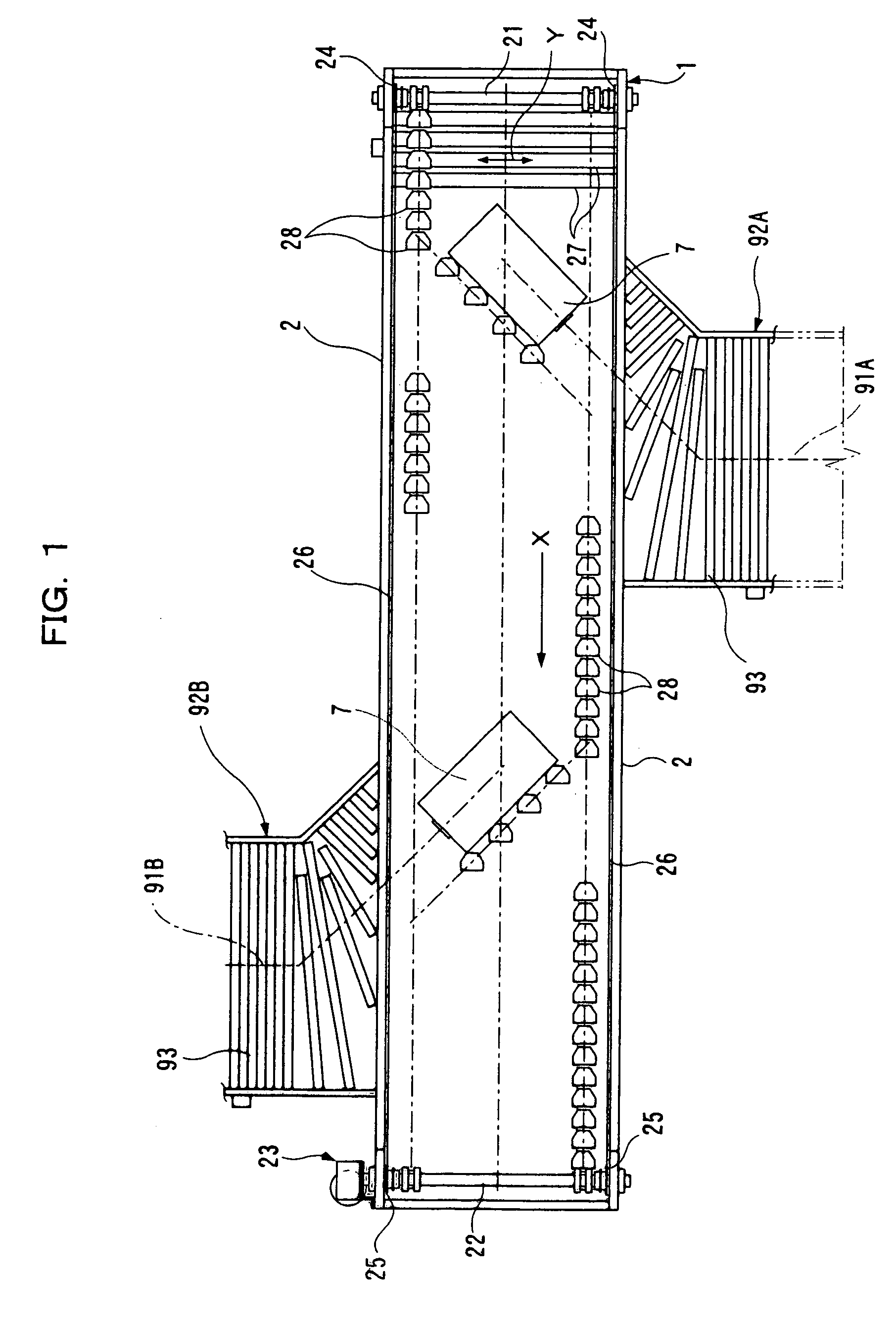
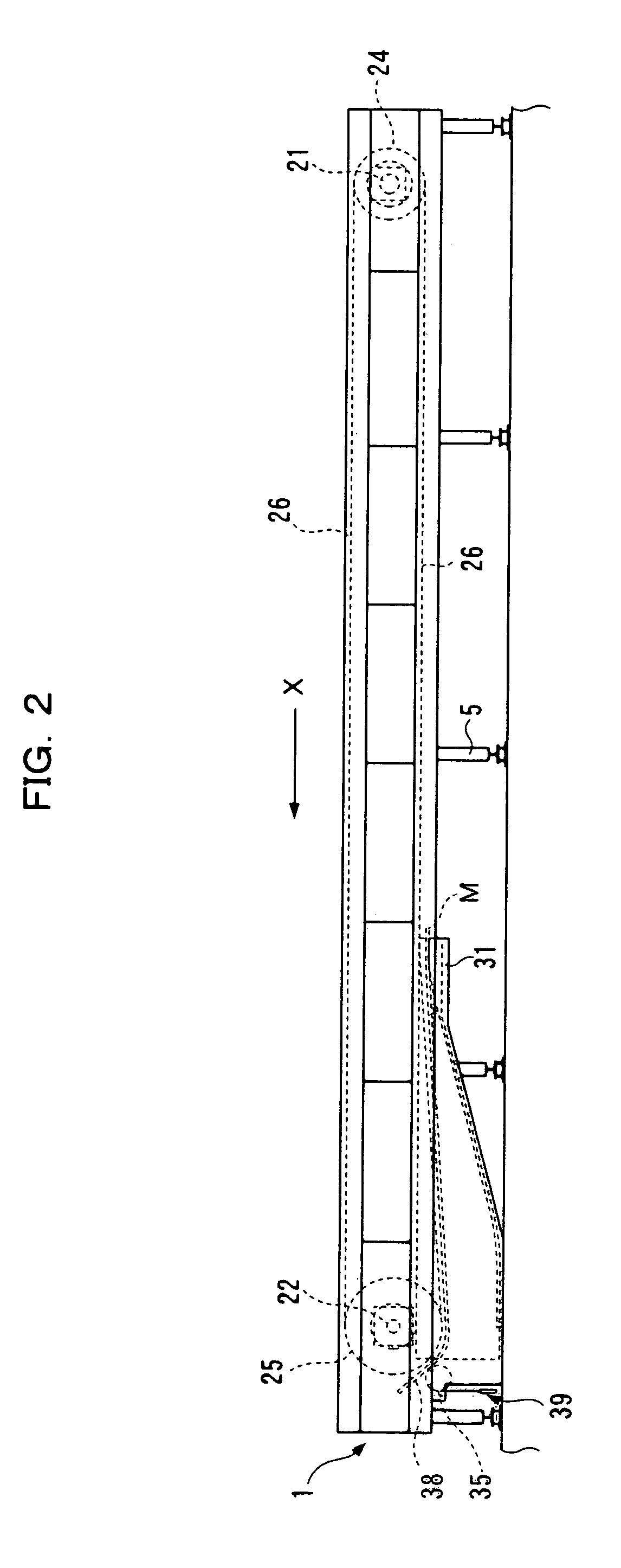
[0031]A slat type conveyor (shoe slide type sorting device) will now be described as a conveyor system of the first embodiment of the present invention based on FIGS. 1 to 7. In the description, a direction for conveying the article by the slat type conveyor is referred to as a conveying direction X and a direction perpendicular to the conveying direction X on a plane is referred to as a horizontal direction Y.
[0032]As shown in FIGS. 1 to 3B, a body frame 1 of the slat type conveyor constitutes a frame of the conveyor system and is arranged, with the conveying direction X being defined as a long direction, and the horizontal direction Y as a short direction (arranged in the conveying direction X of the article). The body frame 1 is constituted by upper frame bars 2 and lower frame bars 3 each arranged as upper and lower pair on both sides of the horizontal direction Y, a longitudinal coupling member 4 for coupling upper and lower frame bars 2, 3, a lateral coupling member (not shown...
second embodiment
[0065]A slat type conveyor (shoe slide sorting device) will now be described as a conveyor system of the second embodiment of the present invention based on FIGS. 8 to 13. The same components as in the first embodiment are denoted with the same reference characters and thus the description thereof will be omitted. In the following description, the direction for conveying the article by the slat type conveyor is referred to as the conveying direction X, and the direction perpendicular to the conveying direction X on a plane is referred to as a horizontal direction Y.
[0066]As shown in FIGS. 11 and 12, an externally upward dovetail 13 is formed at an externally upper end of the standing part 11.
[0067]As shown in FIGS. 8 to 10B, on the driving shaft 22, a stretching sprocket (driving outer sprocket) 17 having a smaller diameter than the driving sprocket 25 and rotated with the right and left driving sprockets 25 is arranged external to the driving sprocket 25 on the left side in the con...
PUM
 Abstract
Description
Claims
Application Information