Module for screening or diverting particulate material and method of producing the module

a technology of particulate material and module, which is applied in the field of modules, can solve the problems of increasing the overall height increasing the cost and complexity of the screening apparatus, and requiring another expensive deviation from the industry standard practice, and achieves the effect of convenient and quick attachmen

Inactive Publication Date: 2006-08-15
WESTERN WIRE WORKS
View PDF33 Cites 52 Cited by
  • Summary
  • Abstract
  • Description
  • Claims
  • Application Information

AI Technical Summary

Benefits of technology

[0021]According to the needs of the industry, one object of the present invention is to provide a module for screening or diverting particulate material which allows for easy and quick attachment between to, for example, the underlying support members of a deck assembly.
[0022]Another object of the present invention is to provide such a module which facilitates ready attachment and removal from the deck assembly without causing damage or destruction to that module or adjacent screening modules.

Problems solved by technology

The intermediate spacer elements, however, add considerably to the cost and complexity of the screening apparatus and increase its overall height.
That requirement represents another expensive departure from standard practices in the industry.
This combination leads to several disadvantages similar to the device of the '099 patent mentioned above.
The '412 patent does not disclose whether or how individual screening modules might be removed and replaced.
The resulting structure is unduly complex, expensive, and increases the height of the deck, among other shortcomings.
Or, more commonly, a user will pry the element off from the top (inlet side) and destroy it in the process.
Either way, the module is rendered useless; a result that is acceptable for modules which are worn out, but wasteful if the module is being replaced merely to change sieve size.
The '412 patent does not disclose any way of removing an individual screening element for replacement, short of disassembling the screening deck.
The securing pin is difficult to pry out of the tube from the inlet side of the screen, although the pin could, perhaps, be driven out from the outlet side of the screen.
In any event, once removed, the pin is loose and therefore subject to loss.
This is a decided risk in the context of screening machines, as it often is impractical or impossible to retrieve an errant securing pin.
Removal of a screening element requires removal of the upper plastic profile, thereby subjecting it to risk of loss like the securing pins of the '821 patent and the like.
Additionally, the clamping structures of the '136 patent extend substantially beyond the edges of the frame, thereby reducing the effective screening area and subjecting the clamping structure itself to excessive wear from abrasion by particulate material being screened.
Since the upper profile section is in locking engagement with the entire extent of the side of the sieve element, it is extremely difficult and time consuming for users to remove and replace individual damaged screen modules.
Furthermore, this removal process often results in unwanted destruction of adjacent undamaged screen modules.
Many reinforced screening modules of the prior art, however, have various types and configurations of discrete internal reinforcing members, which can cause a substantial recycling problem.
For example, those screening modules having an internal reinforcing member are much more difficult and costly to dispose of than screening modules formed of two very different materials of constructions, for example, a polymeric module panel and a metal reinforcing member, which undergo different recycling processes.
Unfortunately, the metallic reinforcement is difficult to separate from the remaining polymeric portion of the screening module panel.
This means that any recycling process for the above-described reinforced module will be time consuming and expensive.
There is no practical way to replace the polymeric material without also replacing the metallic reinforcing member, even though the reinforcing member can have a substantially longer useful life.

Method used


Image

  • Module for screening or diverting particulate material and method of producing the module
  • Module for screening or diverting particulate material and method of producing the module
  • Module for screening or diverting particulate material and method of producing the module

Examples


Embodiment Construction

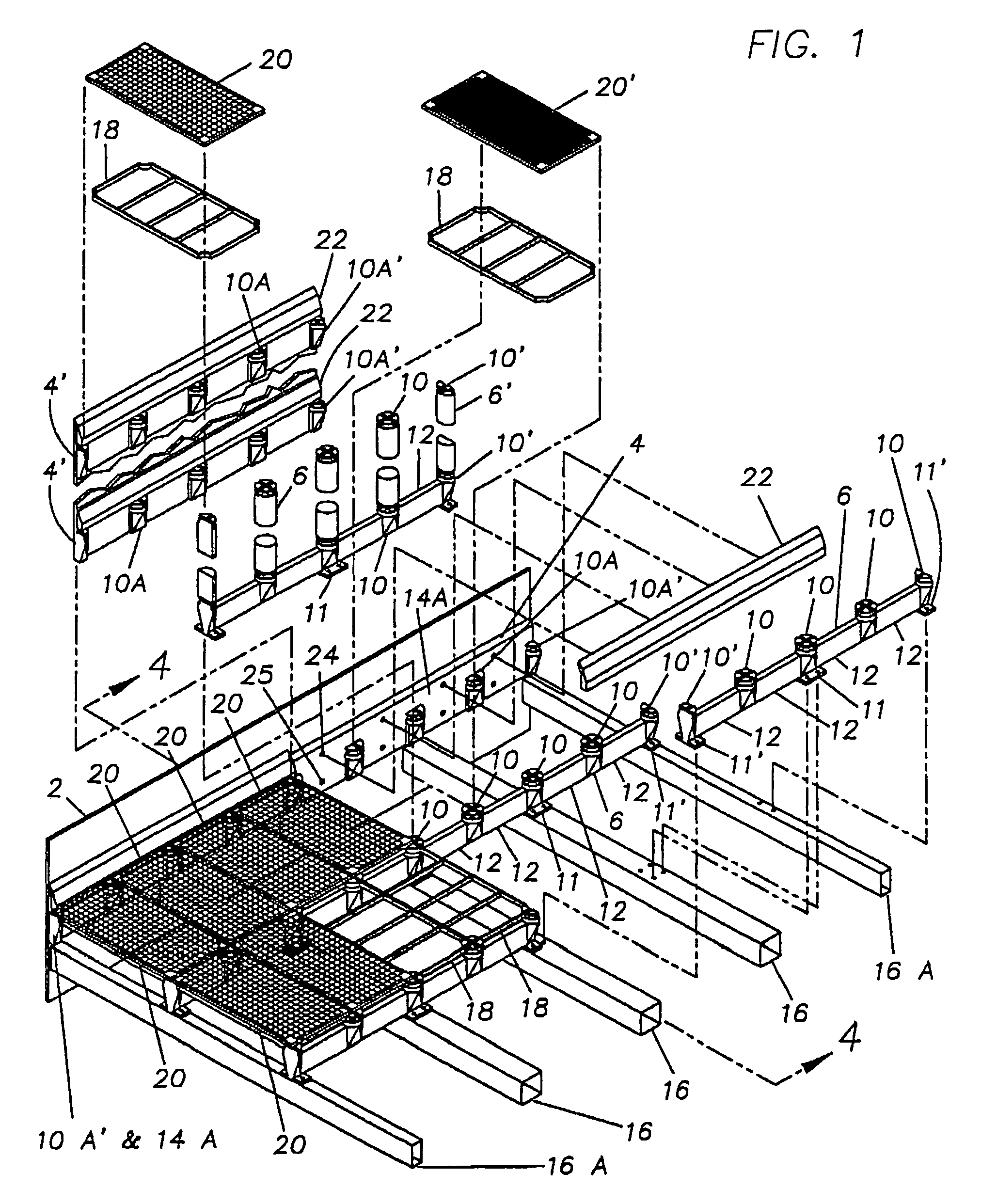
[0059]Referring now to FIG. 1, an overall perspective view is depicted of a deck assembly, denoted “1”, having a particulate flow screening system, having a top side 2, with easily replaceable screening modules according to a preferred embodiment of the present invention. A deck assembly is shown having a sidewall 50, underlying support members 16, and end support members 16A. The support members 16 and 16A support the weight of the particulate screening system and the particulate material being screened.

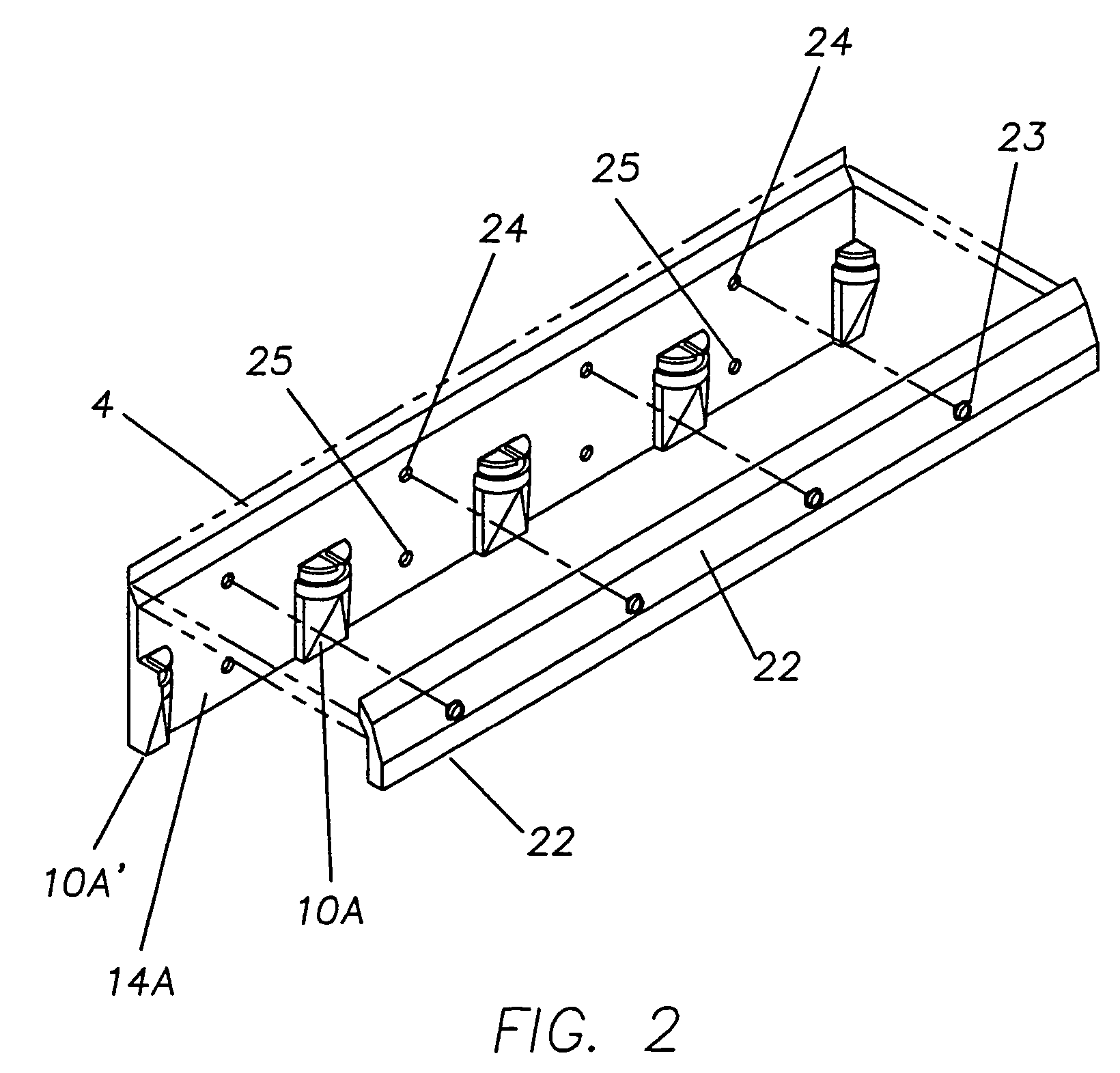
[0060]A preferred embodiment of the particulate screening system of this invention includes a wall mounting post assembly 4 (or 4′ in the multi-screen version of an alternative embodiment) having one or more half posts 10A, one or more quarter posts 10A′, and one or more wall mounting pieces 14A. Bolts secure each wall-mounting piece 14A to the sidewall 50 through boltholes 25. The shield 22 is connected to the wall-mounting piece 14A by being interlockingly snap fit into holes 24. ...


PUM


Abstract

A module is provided for screening or diverting particulate material. A method for producing a module for screening or diverting particulate material is also provided. Each module comprises either a screening member having an array of sieve apertures of a predetermined size defined therein for allowing particulate material up to the predetermined size to pass through the module or a diverting member or redirecting the flow path of the particulate material. A plurality of posts removably and interlockingly supports at least one reinforcing support frame and at least one module. Each reinforcing support frame is interlockably mounted onto the posts, and is readily detachable therefrom. Each module is disposed on the interlocking posts and is mounted onto, and readily detachable from, the reinforcing support frame. Each module is further positioned on the frame such that any particulate material passing through the module passes through the frame.

Description

RELATED APPLICATION[0001]This is a divisional of U.S. Ser. No. 09 / 904,197, filed on Jul. 11, 2001, now U.S. Pat No. 6,886,697, which is a continuation application of U.S. Ser. No. 09 / 503,961, filed on Feb. 14, 2000, now U.S. Pat. No. 6,267,246.BACKGROUND OF THE INVENTION[0002]This invention relates to modules for screening particulate material by size, or for diverting the particulate material, to methods of producing such particulate material screening systems, and to reinforcing support frames for such screening modules.[0003]Various modes for connecting a screening module to an underlying frame to form a screening deck are known in the prior art. Some methods require spacers or adapter bars between the screening module and the deck support structure. An example of such an arrangement is shown in U.S. Pat. No. 4,409,099 (“the '099 patent”). The '099 patent shows screening modules supported only at their corners on spacer modules so that the screening element is spaced above the su...

Claims


Application Information

Patent Timeline
Patent Type & Authority Patents(United States)
IPC IPC(8): B07B1/49B07B1/46
CPCB07B1/4618B07B1/469B07B1/4645B07B1/4627
Inventor RUSSELL, LYNN A.ASKEW, TERRY R.GOLD, JACK COLEMAN
Owner WESTERN WIRE WORKS
Why Eureka
Try Eureka