Cartridge-type bearing seal for machine tool spindle

a technology of bearing seals and machine tools, which is applied in the direction of engine seals, leakage prevention, machines/engines, etc., can solve the problems of prior patents that did not disclose or suggest a specific structure, and the downtime can have critical adverse effects on the overall spindle efficiency and throughput, so as to facilitate the replacement of worn bearing seals, facilitate the retrofitting of bearing seals, and improve the effect of sealing

Inactive Publication Date: 2006-08-15
SETCO SALES
View PDF11 Cites 11 Cited by
  • Summary
  • Abstract
  • Description
  • Claims
  • Application Information

AI Technical Summary

Benefits of technology

[0010]According to one aspect of the invention, this structure includes a ring-shaped stator section with a circumferential, radially inwardly extending collar and a ring-shaped rotor section with at least three arcuately spaced tangs sized in a complementary manner to engage the collar and hold the sections together, in a manner which permits relative rotation about a common axis. The collar of the stator section is sufficiently deflectable, in a radially outward direction, that the sections can be pushed together and retained by applying force in the desired axial direction. Thus, the collar and the tangs provide a snap fit.
[0016]When connected to form the cartridge, the combined stator and rotor sections define a radial inside surface and a radial external surface, and a fluid flow path therebetween which generally extends from the inside circumferential surface to the outside surface. The annular fluid path traverses an annular lip, and thereafter, an annular space which resides between the collar of the stator section and the body of the rotor section, and the tangs of the rotor section, and then traverses radially outwardly from the cartridge. Pressurized purge fluid entering the flow path at the inside surface will move past the annular lip in a radially outward direction, then outwardly past the collar of the stator section, and then outwardly from the cartridge in a radial direction. This pressurized fluid flow prevents contaminate ingress into the spindle housing, thereby protecting the bearings of the spindle. Moreover, this structure inhibits contaminant ingress in a manner which does not hinder the effectiveness or operability of the spindle, and specifically the rotatability of the rotor relative to the stator.

Problems solved by technology

Such downtime can have critical adverse effects on overall spindle efficiency and throughput.
However, those prior patents did not disclose or suggest a specific structure for achieving the benefits of the prior invention with a wide variety of spindles of various size and shape.

Method used


Image

  • Cartridge-type bearing seal for machine tool spindle
  • Cartridge-type bearing seal for machine tool spindle
  • Cartridge-type bearing seal for machine tool spindle

Examples


Embodiment Construction

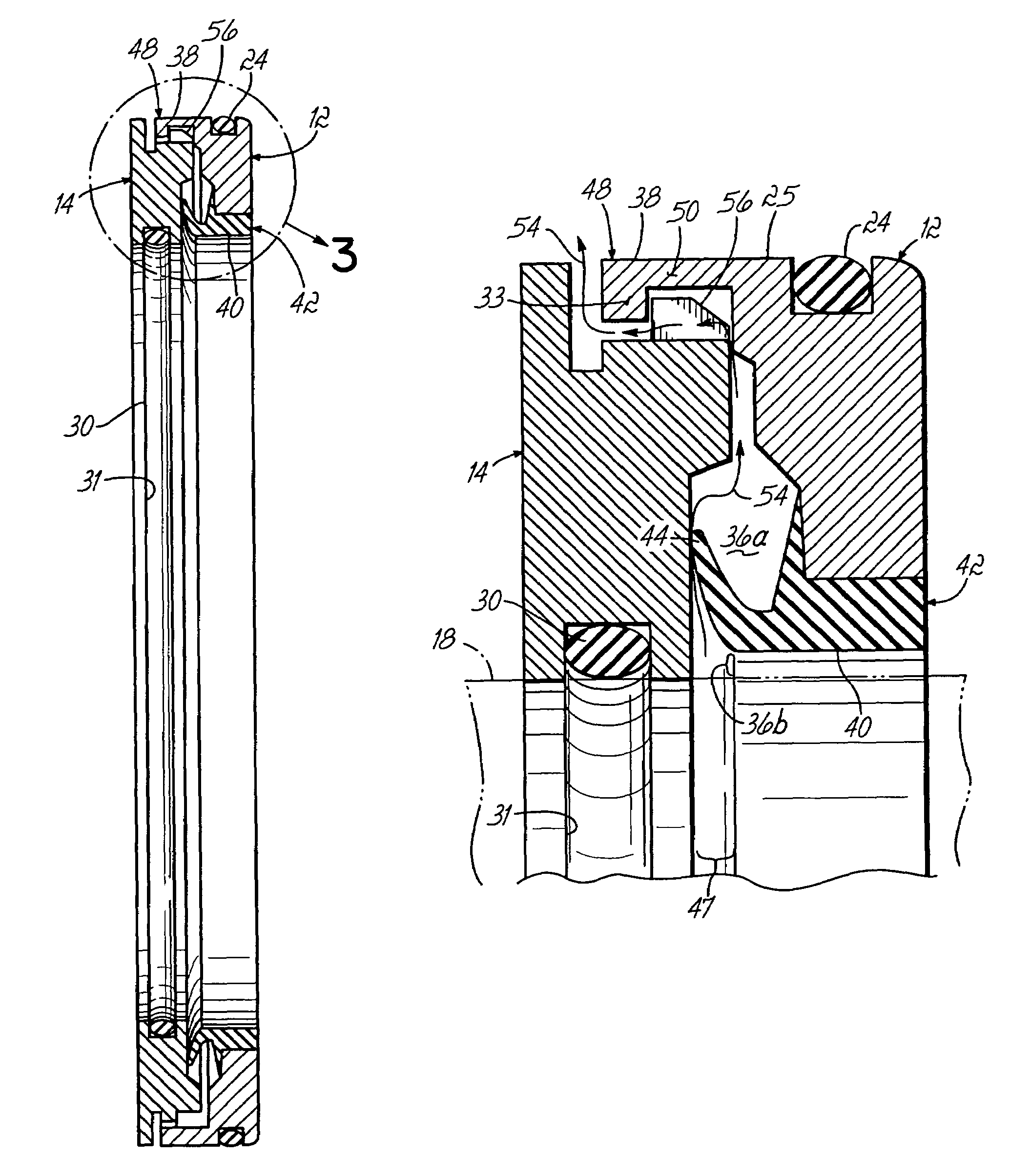
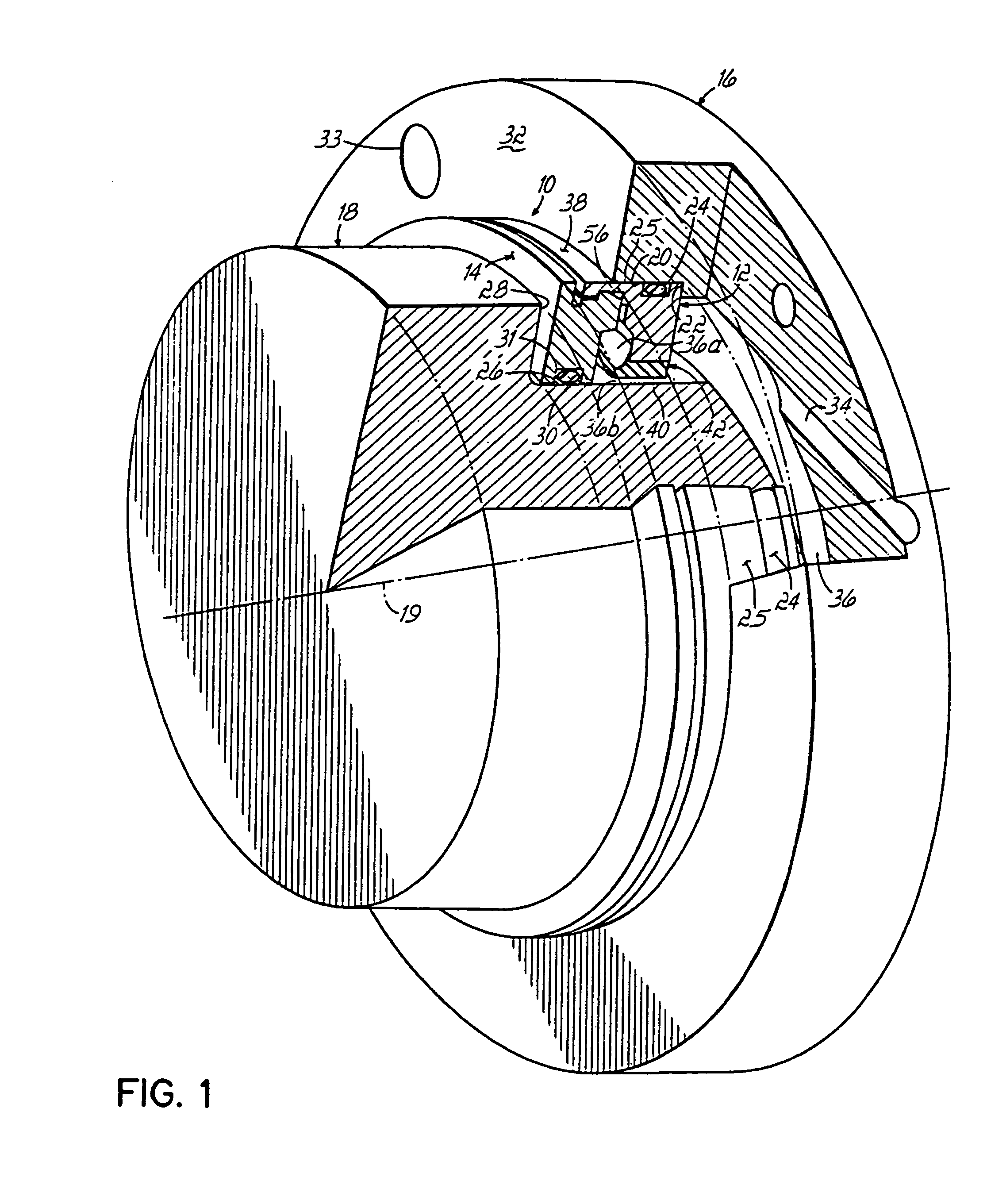
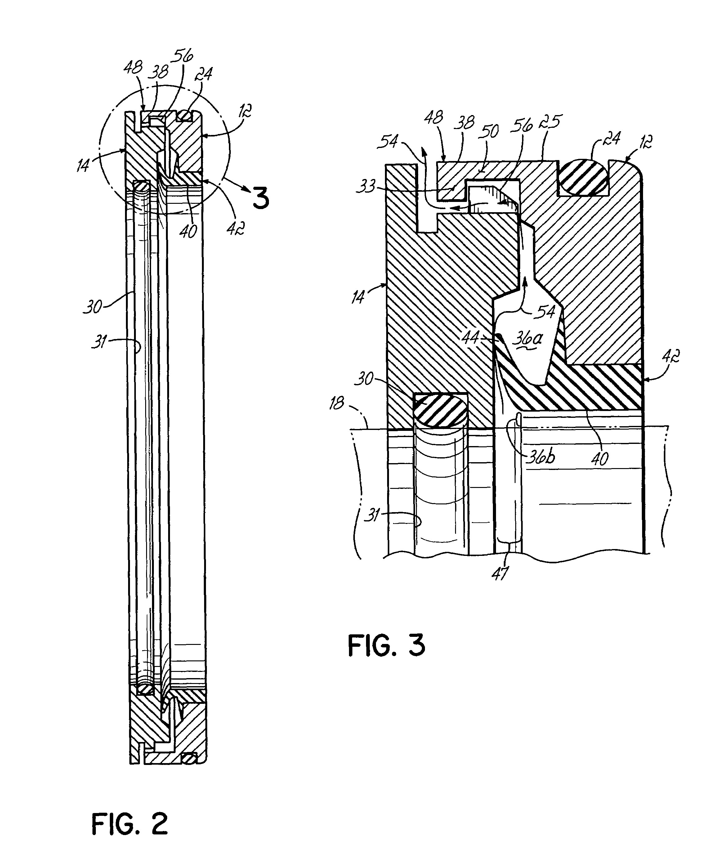
[0026]FIG. 1 shows a cartridge bearing seal constructed in accordance with a first preferred embodiment of the invention. This patent expressly incorporates by reference herein the disclosures of previously mentioned U.S. Pat. Nos. 5,727,095; 5,980,155; and 6,217,219 B1, all entitled “Bearing Seal With Uniform Fluid Purge.” As noted above, the cartridge bearing seal of this invention makes the inventive bearing seal of those prior patents more readily available to a wider variety of spindle structures. And this inventive cartridge bearing seal is particularly suitable for retrofitting in-place spindles.

[0027]FIG. 1 shows that the bearing seal of this invention comprises an annular cartridge 10 with interconnected first and second sections 12 and 14, respectively. As shown in FIG. 1, the first section 12 is a stator section, and it is fixedly mounted to a stator 16, while second section 14 is a rotor section which is fixedly mounted to a rotor 18. The rotor 18 rotates relative to the...


PUM


Abstract

A cartridge type bearing seal facilitates the prevention of contaminant ingress between a spindle rotor and a spindle housing, particularly in situations where a circumferentially uniform fluid pressure is generated within the annular volume of the spindle housing. The cartridge includes ringlike rotor and stator sections which can be compressed axially to snap fit together, in a manner which enables relative rotation about a common axis. When interconnected, the sections define an inside surface and an outside surface, and a fluid flow path which extends radially outwardly therebetween, and which traverses a collar and tangs construction which enables the snap fit connection. The tangs are arcuate in shape and spaced equidistantly around the axis. The total arcuate space occupied by the tangs is relatively small, compared to the total arcuate space residing between the tangs, and bounded by the two sections adjacent the collar. This structure allows the pressurized purge fluid to flow outwardly from the cartridge during use, to prevent contaminant ingress during operation of the spindle. This construction may be readily adapted to accommodate a spindle of virtually any size or shape, at relatively low cost, and is particularly suitable for retrofitting an existing spindle which has experienced a failed seal.

Description

FIELD OF THE INVENTION[0001]This invention relates to a bearing seal for a machine tool spindle, and more particularly to a cartridge which houses the bearing seal.BACKGROUND OF THE INVENTION[0002]The assignee of the present invention, Setco Sales Company, owns U.S. Pat. Nos. 5,727,095, 5,980,115 and 6,217,219 B1, all of which are entitled “Bearing Seal With Uniform Fluid Purge,” and directed to a unique bearing seal which has proved tremendously successful in increasing the reliability of spindles. Setco sells this patented bearing seal under the trademark AIRSHIELD®. These Setco patents are incorporated herein by reference, in their entireties.[0003]According to one aspect of the prior invention, the bearing seal includes an annular cap located at a first end of a bearing housing, where a shaft exits therefrom. The cap has an internal surface which defines an annular internal volume, and a passage formed therethrough which tangentially intersects the annular volume. This structure...

Claims


Application Information

Patent Timeline
Patent Type & Authority Patents(United States)
IPC IPC(8): F16J15/40F16J15/447F16J15/16F16J15/34
CPCF16J15/162F16J15/348F16J15/3456
Inventor HOETING, STEPHEN C.HODGE, BOBBY L.
Owner SETCO SALES
Why Eureka
Try Eureka