Steering system with tilt control

a technology of tilt control and steering system, which is applied in the direction of steering parts, vehicle components, transportation and packaging, etc., can solve the problem that the seat occupant stepping down the foot brake pedal cannot make the shift selection from parking, and achieve the effect of ensuring safety

Inactive Publication Date: 2006-08-15
FUJI KIKO CO LTD
View PDF10 Cites 18 Cited by
  • Summary
  • Abstract
  • Description
  • Claims
  • Application Information

AI Technical Summary

Benefits of technology

[0013]It is another object of the present invention to provide the steering system that is free from causing an interference to a steering column's cover with an instrument panel when a steering wheel is popped up, thus securing safety.

Problems solved by technology

Moreover, the seat occupant even stepping on the foot brake pedal cannot unlock the shift lever locking means unless the steering wheel is returned to a driving position completely.On the other hand, the steering wheel returned to the driving position completely may allow the seat occupant to unlock the shift lever locking means by stepping on the foot brake pedal.
With the steering wheel in an inoperable position, the seat occupant stepping down the foot brake pedal cannot make the shift selection from parking to other speed range, even when the vehicle is in the idle state or the ignition key is turned on.
With the steering system according to Japanese Patent Unexamined Publication No. 2000-71798 (=JP2000071798), however, a pop up mechanism popping up the steering wheel greatly upward in the vehicle's stop and the like may cause an interference to a steering column's cover with an instrument panel which is disposed in front of the seat occupant in the vehicle.

Method used


Image

  • Steering system with tilt control
  • Steering system with tilt control
  • Steering system with tilt control

Examples


first embodiment

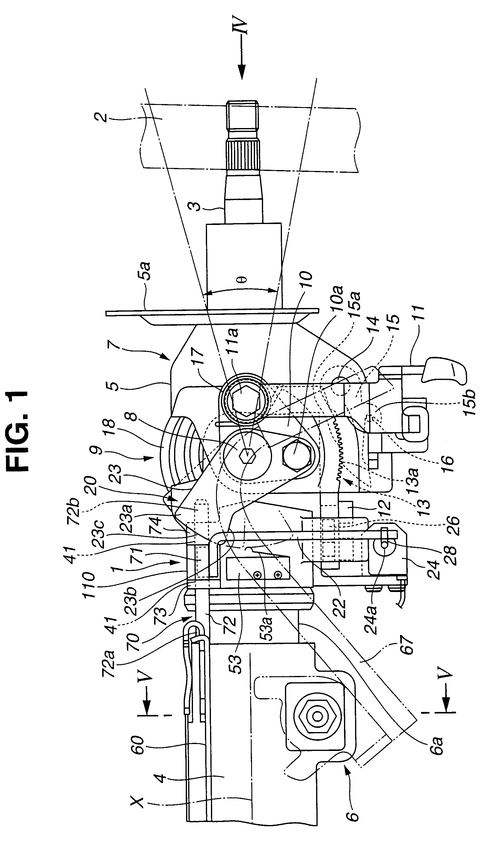
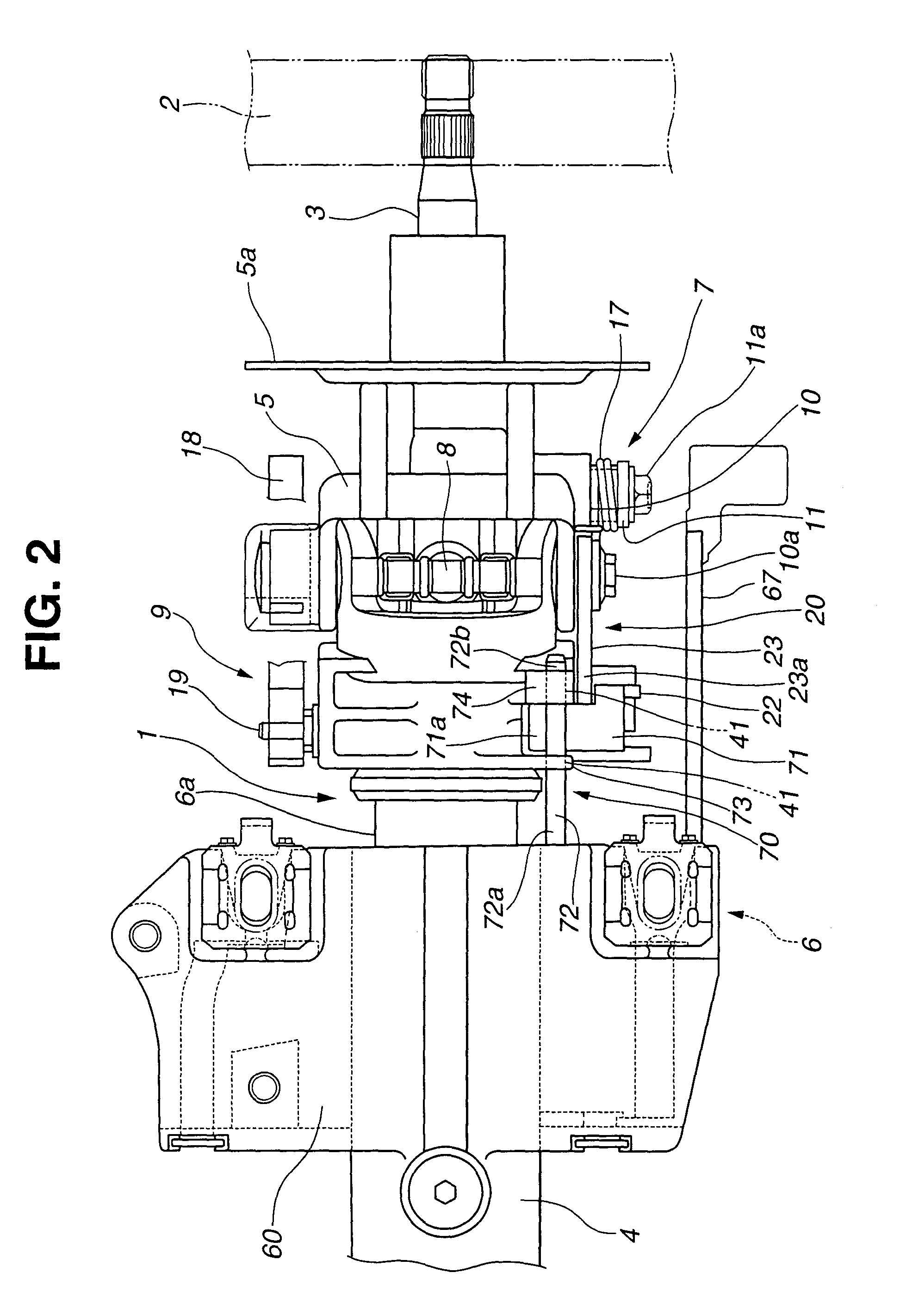
[0048]FIG. 1 to FIG. 3 show a steering system applied to a vehicle equipped with an automatic transmission, according to the present invention.

[0049]The steering system includes a steering column 1, an upper shaft 3, and a lower shaft (not shown). The steering column 1 supports a steering wheel 2 to a vehicular body. The upper shaft 3 is inserted into a first end (right in FIG. 1 and FIG. 2) of the steering column 1, and has an upper end (right in FIG. 1 and FIG. 2) which is exposed outward and fitted with the steering wheel 2. The lower shaft (not shown) has an upper end connected with a lower end (left in FIG. 1 and FIG. 2) of the upper shaft 3 via a first universal joint (not shown), and a lower end connected with a steering gear (not shown) via a second universal joint.

[0050]The steering column 1 is separated into a stationary column portion 4 on the steering gear (not shown)'s side and a movable column portion 5 on the steering wheel 2's side.

[0051]The stationary column portion...

second embodiment

[0125]FIG. 9 and FIG. 11 show a partly broken side view of an essential part of a steering system, according to the present invention.

[0126]The steering system includes a movable column portion 82 and a stationary column portion 81. The movable column portion 82 is disposed on a steering wheel's side, and is so supported via a tilt hinge shaft 84 to a hinge bracket 110 as to pivot substantially upward and downward. The hinge bracket 110 connects to a telescope jacket 83. The telescope jacket 83 is connected to the stationary column portion 81 in such a manner as to extend and shrink (telescope).

[0127]A control portion 112 fixed to the stationary column portion 81 extends with a certain length toward the hinge bracket 110 substantially in parallel to an axial line of a telescope jacket 83. The control portion 112 has a head end portion 112b (free end) inserted into a guide hole 94 which is defined substantially through the hinge bracket 110. The hinge bracket 110 is a part which is m...


PUM


Abstract

A steering system includes:
    • a tilt mechanism including a pivotal shaft which extends in a sidewise direction of the vehicle, the tilt mechanism being adapted to pivot the movable column portion upward and downward around the pivotal shaft, the tilt mechanism controlling the movable column portion to be secured in a certain upper pivotal position and a certain lower pivotal position;
    • a telescope mechanism adapted to pull out and push in in a forward-backward direction of the vehicle the movable column portion including the pivotal shaft;
    • a pop up mechanism for allowing the movable column portion to make a popping up over an uppermost pivotal position defined by the tilt mechanism; and
    • a pop up mechanism controlling mechanism for controlling the popping up of the movable column portion by the pop up mechanism until the movable column portion pulled out by the telescope mechanism has a certain length.

Description

BACKGROUND OF THE INVENTION[0001]1. Field of the Invention[0002]The present invention relates to a steering system having a tilt mechanism and a pop up mechanism both for controlling tilting of a steering wheel, with some parts shared by the tilt mechanism and the pop up mechanism. Moreover, the steering system under the present invention includes a telescope mechanism for moving the steering wheel substantially in a forward-backward direction.[0003]2. Description of the Related Art[0004]For improving seat occupant's comfort (namely, getting in and getting off the vehicle with ease), various types of steering systems are proposed, including one that has a steering wheel capable of popping up to a certain position when the seat occupant gets off the vehicle and moving back to a driving position after the seat occupant gets in the vehicle.[0005]Recently, another steering wheel having a greater popping up angle for further improving the seat occupant's comfort is in practical use, as i...

Claims


Application Information

Patent Timeline
Patent Type & Authority Patents(United States)
IPC IPC(8): B62D1/183B62D1/18B62D1/181B62D1/184B62D1/187
CPCB62D1/184B62D1/183
Inventor KINOSHITA, SATOSHISHIMIZU, YOSHIYUKISUGIYAMA, KAZUHIROMORIYA, YOSHIYUKIUESAKA, YOTA
Owner FUJI KIKO CO LTD
Why Eureka
Try Eureka