
Image pickup lens, image pickup apparatus and method for forming image pickup lens

Inactive Publication Date: 2006-08-15
KONICA CORP
View PDF9 Cites 25 Cited by
  • Summary
  • Abstract
  • Description
  • Claims
  • Application Information

AI Technical Summary

Benefits of technology

[0040]According to the image pick-up lens mentioned in Structure 2-(1) and 2-(2), flow of resin to the lens is improved by installing a gate on the flange part, for example, at the time of injection molding. While making an effective use of this advantage, the lens part is positioned in the direction at right angles to the optical axis, using the outer surface of the supporting part arranged on the side close to the optical axis with respect to the aforementioned flange part. In the step of positioning, this makes it possible to ignore the impact of burrs or flashes which may occur to the gate, with the result that positioning accuracy is improved. The supporting part can be extended to each side in the direction of optical axis.
[0133]This method provides easier adjustment of the end of the supporting part to the focusing point of the lens, as compared to the case where the lens and supporting part are molded by a single mold or by multiple molds which cannot make a relative movement in the direction of optical axis. Merely placing it on the image pick-up device allows the image pick-up lens to be molded, which permits precision adjustment of the focusing point to the photo-electric conversion unit.

Problems solved by technology

At present, however, the weight of a cellular phone will be increased if the cellular phone is equipped with the function of a large-sized digital still camera which is much larger than the cellular phone, with the result that the phone cannot be easily carried.
In addition to this problem, the manufacturing cost will be increased that much.
This raises the problem of how to make this adjustment.
For example, when the image pick-up device and image pick-up optical system are to be installed on one and the same base board, it can be said to be difficult to install the photo-electric conversion unit of the image pick-up device at the focusing position of the image pick-up optical system with high precision due to such factors as variations in the thickness of adherent used for mounting on the base board or variations in the dimensions of component parts.
This will raise the manufacturing cost.
In addition to the above-mentioned high cost problems, this configuration will require a lot of time in assembling these parts, and the relative position between the image pick-up device 110 and lens 106 must be adjusted by rotating the lens body tube 105 at the time of assembling.
However, this method raises the problem of what profile the lens supporting part should have.
These legs, however, has a problem of being easily deformed by external force.
If legs are deformed, a deviation is caused between the photo-electric conversion unit of the image pick-up device and lens focusing point, and this may deteriorate the image quality.
Another problem is how to manufacture an image pick-up lens where the periphery of a lens is extended in the direction of optical axis.
If injection molding is used, however, burrs are likely to be formed on the split portion of the mold.
When the gate is cut off, burrs are also likely to occur.
Depending on the position of these burrs, the assembling precision may be deteriorated, with the result that function of the image pick-up device may not be fully performed.
A further problem is how to adjust the positional relationship between the surface formed by the tip of supporting part and lens surface in order to ensure precise layout of the photo-electric conversion unit of the image pick-up device.

Method used


Image

  • Image pickup lens, image pickup apparatus and method for forming image pickup lens
  • Image pickup lens, image pickup apparatus and method for forming image pickup lens
  • Image pickup lens, image pickup apparatus and method for forming image pickup lens

Examples


Embodiment Construction

[0153]The following describes the preferred embodiments according to the present invention with reference to drawings:

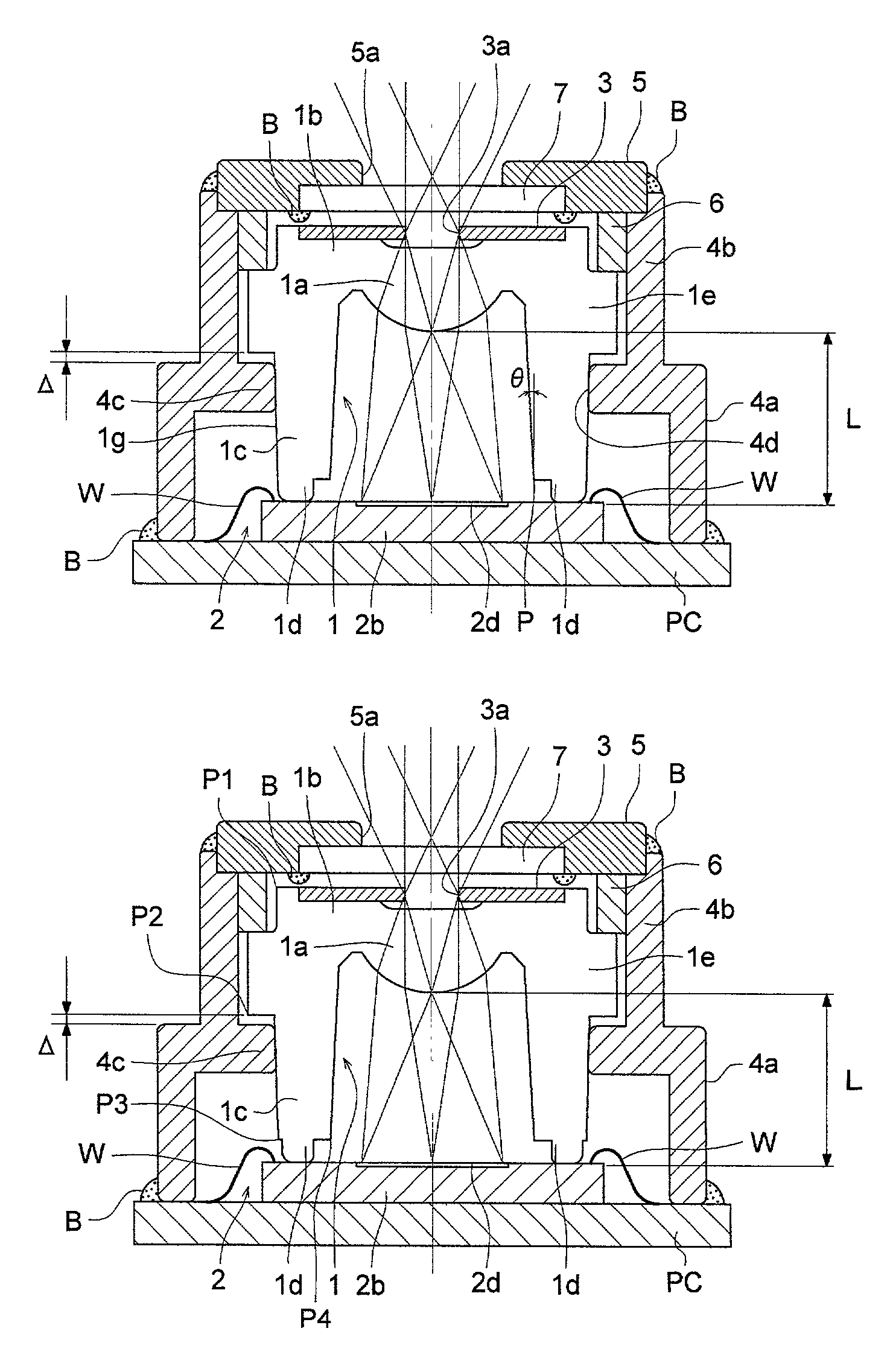
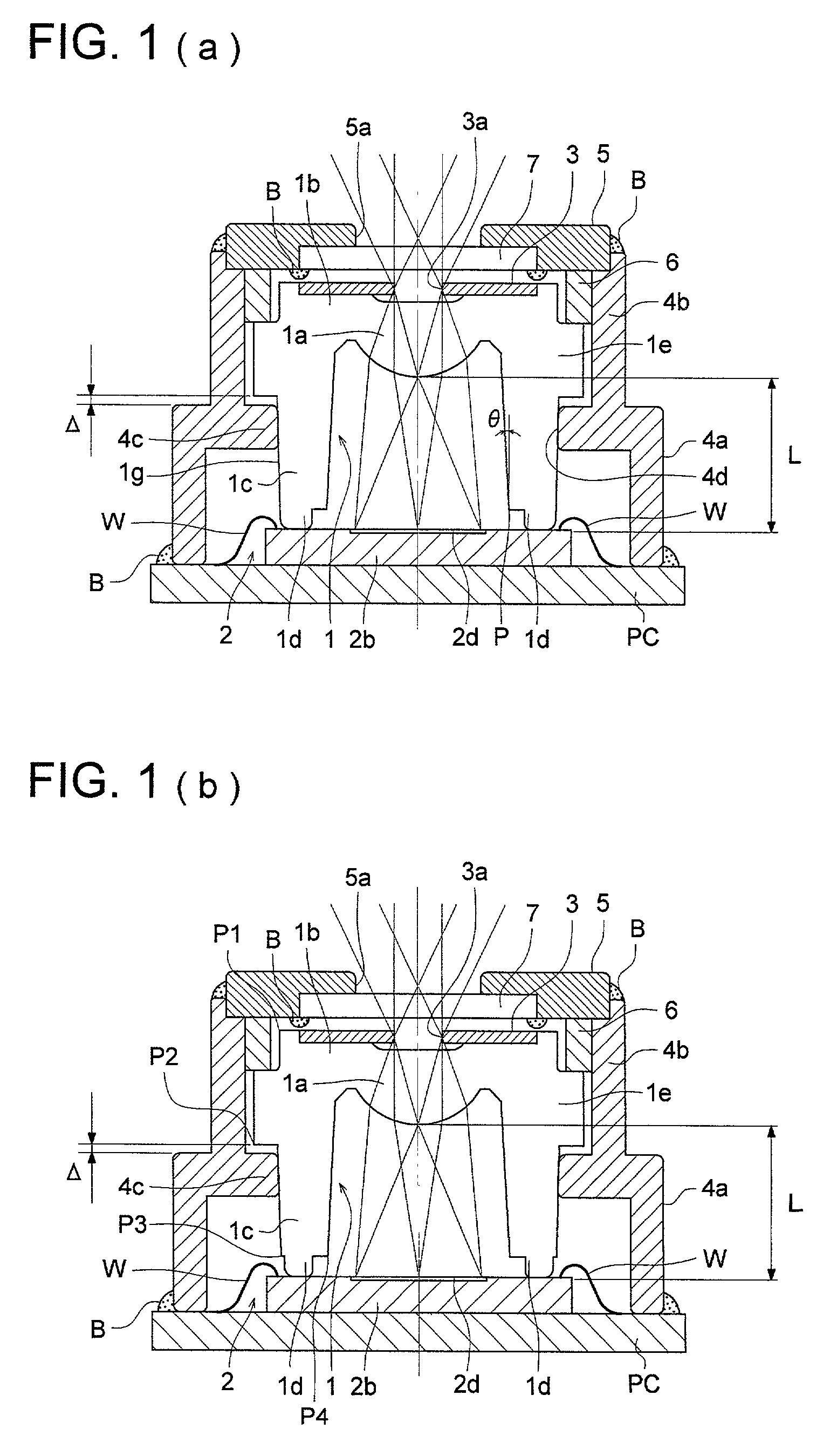
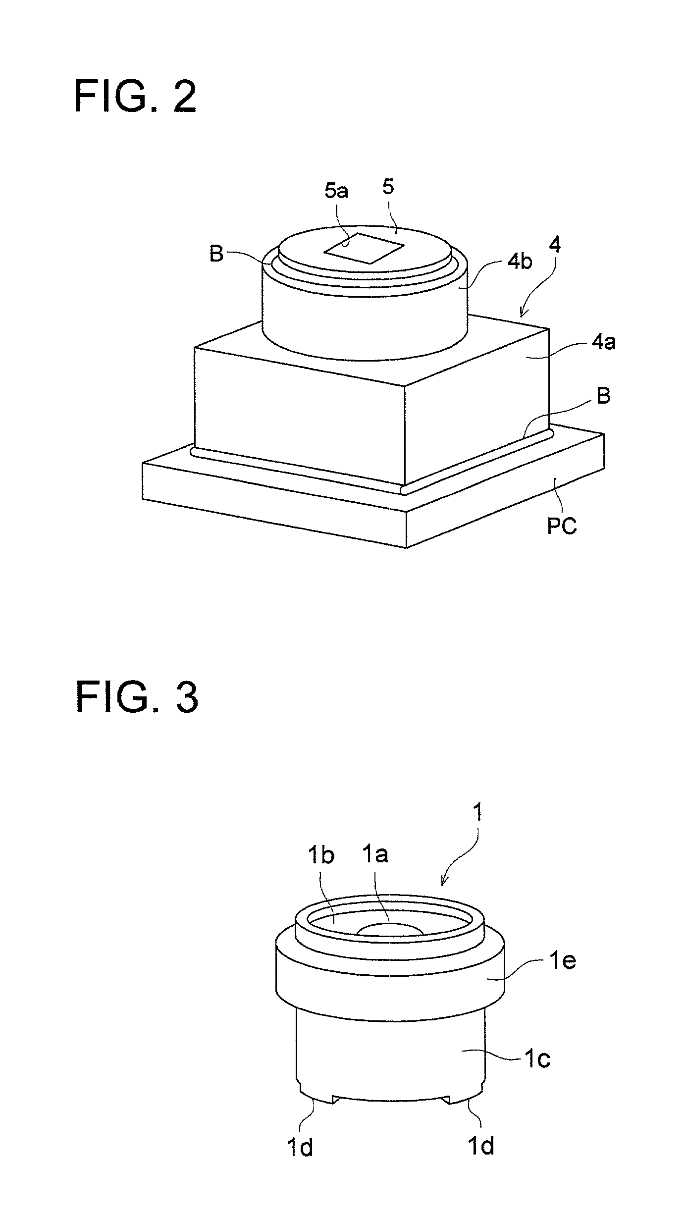
[0154]Each of FIGS. 1(a) and 1(b) is a cross sectional view of the image pick-up apparatus as an embodiment of the present invention. FIG. 2 is a perspective view of the image pick-up apparatus given in FIG. 1. FIG. 3 is a perspective view of the image pick-up lens. Each of FIGS. 4(a) to (d) is a bottom view of the image pick-up lens. Each of FIGS. 5(a) and 5(b) is a top view of the image pick-up device.

[0155]The image pick-up lens is made of transparent plastic material, and, as shown in FIG. 1, comprises a cylindrical supporting part 1c, four contact portion ld formed on the tip of a supporting part 1c as its component thereof, a flange 1e formed around the top end of the supporting part 1c, a plate-formed top surface 1b blocking the top end of the supporting part 1c, and a convex lens 1a formed at the center of the top surface 1b, which are integrally formed in on...


PUM


Abstract

The present invention relates to an image pick-up lens, an image pick-up apparatus comprising the image pick-up lens and a producing method of the image pick-up lens, and the image pick-up lens comprising: a lens part to form an image point of an object point at predetermined distance; and a supporting part to support the lens part and integrally formed with the lens part in a tubular form extended from the periphery of the lens part along the optical axis of the lens part, and the tip end of the tubular form is included in an ideal plain surface perpendicular to the optical axis of the lens part, wherein the image point is located in the ideal plain surface.

Description

FIELD OF THE INVENTION[0001]The present invention relates to an image pick-up lens, an image pick-up apparatus and a method for forming the image pick-up lens; and particularly to an image pick-up lens and an image pick-up apparatus which can be mounted on a cellular phone or a personal computer, and to a method for forming such a lens and apparatus.BACKGROUND OF THE INVENTION[0002]In recent years, easy handling of digital image data has been realized by improved performance of the CPU and development of image processing technique. Especially the cellular phones and PDA (Personal Digital Assistance) provided with a display unit capable of image display have become available on the market and the drastic improvement in radio communication speed can be expected in the very near future. Accordingly, frequent transfer of image data is considered to be made among cellular phones and PDA.[0003]At present, a subject is converted into an image data by a digital still camera or the like, and...

Claims


Application Information

Patent Timeline
IPC IPC(8): G02B7/02G02B13/00
CPCG02B7/02G02B13/002G02B7/022G03B30/00
Inventor YAMAGUCHI, SUSUMUHATTORI, HIROYUKI
Owner KONICA CORP
Learn More