
Method of detecting a defect area of a disk

a defect area and disk technology, applied in the field of methods of detecting a defect area of a disk, can solve the problems of data recording being re-started from the beginning, not rewritable, and the worst effect of data recording

Inactive Publication Date: 2006-08-15
HITACHI LG DATA STORAGE KOREA
View PDF7 Cites 93 Cited by
  • Summary
  • Abstract
  • Description
  • Claims
  • Application Information

AI Technical Summary

Benefits of technology

[0009]It is an object of the present invention to provide a method of detecting a defect area of a writable disk more exactly in order to ensure successful data writing on a defect area through timely recording speed reduction.

Problems solved by technology

Especially, a center area of a defect zone has the worst effect on data recording.
In the case that a recording operation is abnormally ended, it is impossible to resume data recording from the abnormally-ended recording position, therefore, data recording must be re-started from the beginning inevitably.
However, because a once-writable disk, namely, a CD-R can not be rewritable, it is obliged to be thrown away.
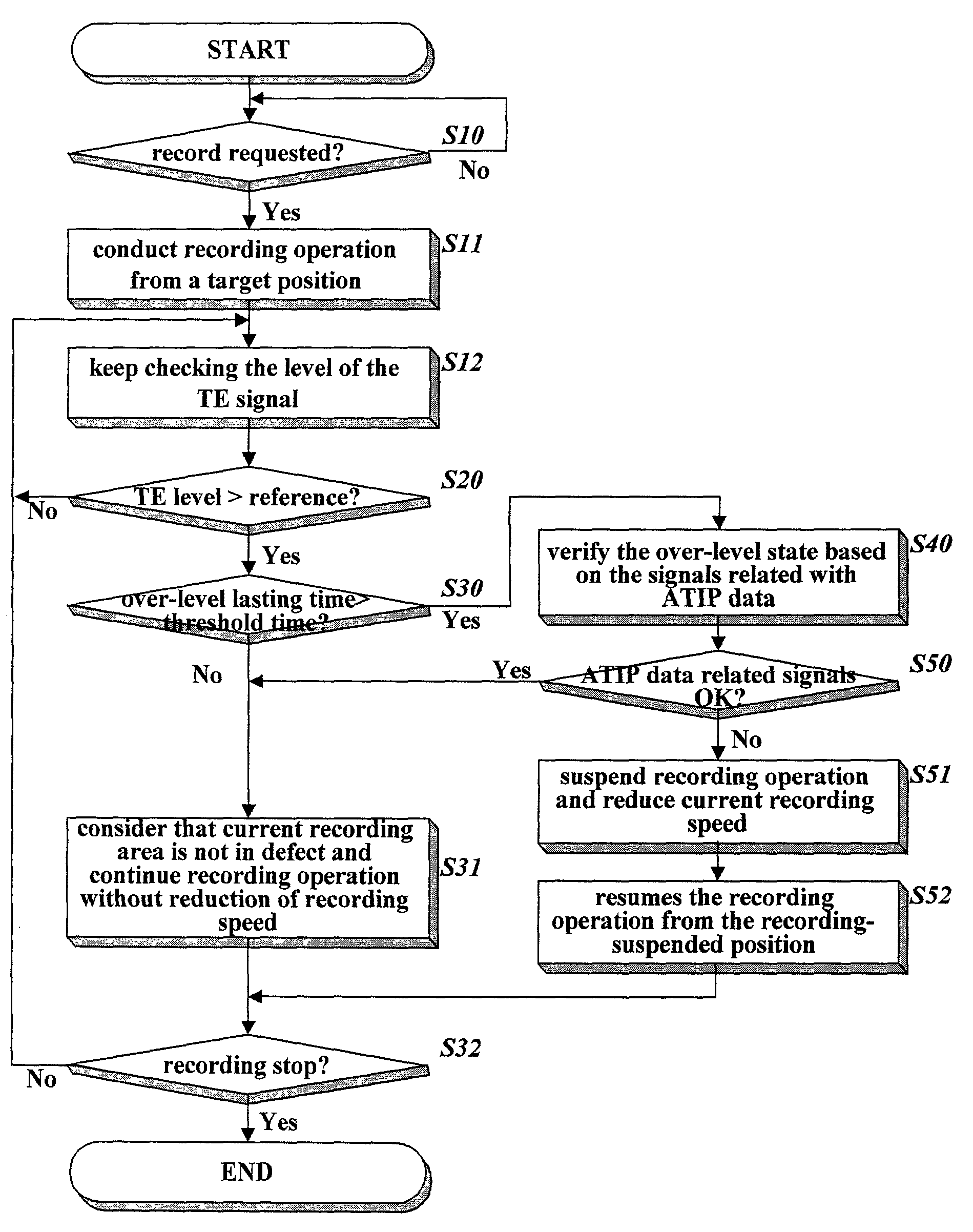
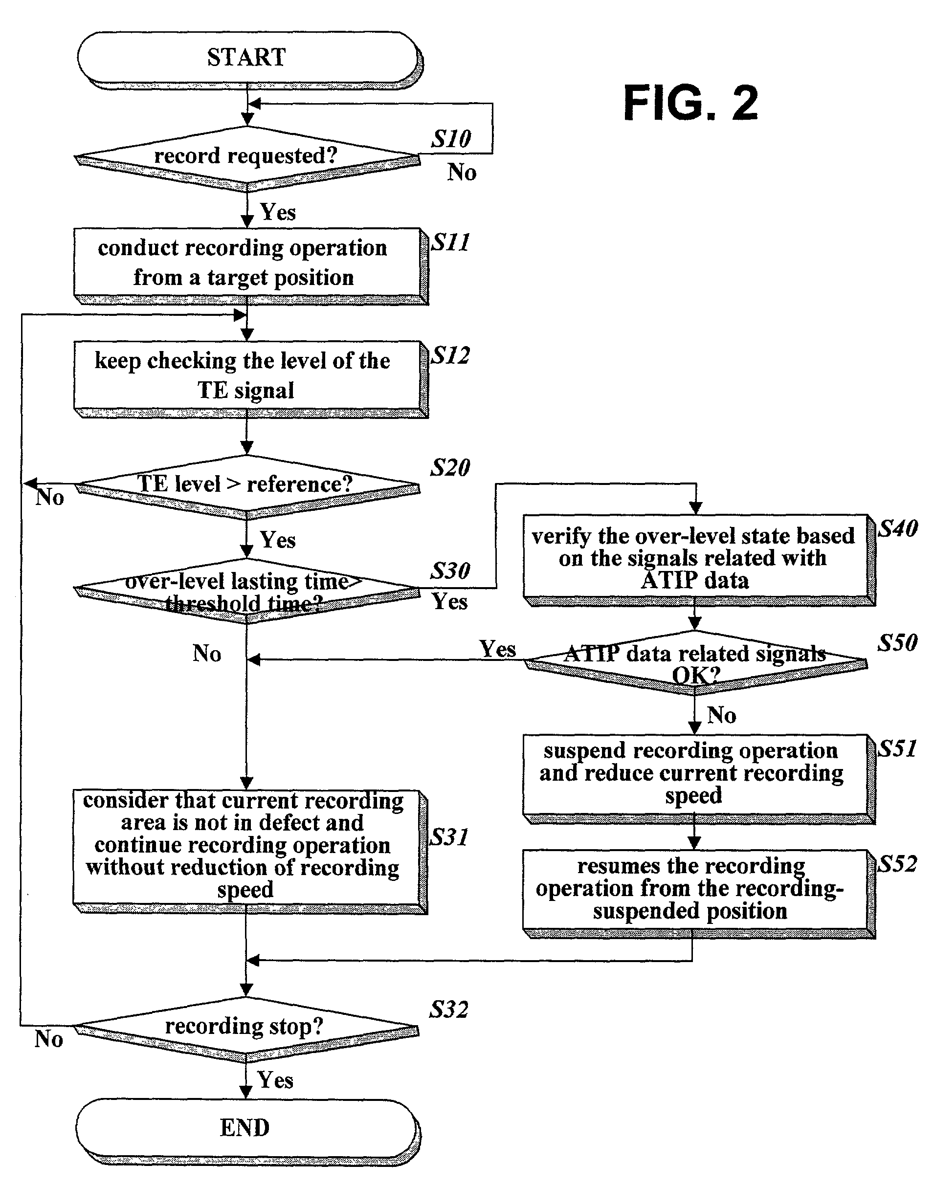
In the method using level of a TE signal, the level of a TE signal is always being monitored while data is recorded on a writable disk at a predetermined recording speed, and if the monitored level is greater than a preset limit level a current recording area is regarded as defect.
In other words, if the TE signal looks unstable a current recording area is regarded as defect so that a current recording speed is decreased to adequate one.
However, the TE signal may be unstable instantaneously due to a mechanical shock or disturbance from the outside, therefore, if only level of the TE signal is used in determination of a defect area, a normal recording area may be mistakenly regarded as defect, which leads unnecessary writing speed reduction.

Method used


Image

  • Method of detecting a defect area of a disk
  • Method of detecting a defect area of a disk
  • Method of detecting a defect area of a disk

Examples


Embodiment Construction

[0019]In order that the invention may be fully understood, a preferred embodiment thereof will now be described with reference to the accompanying drawings.

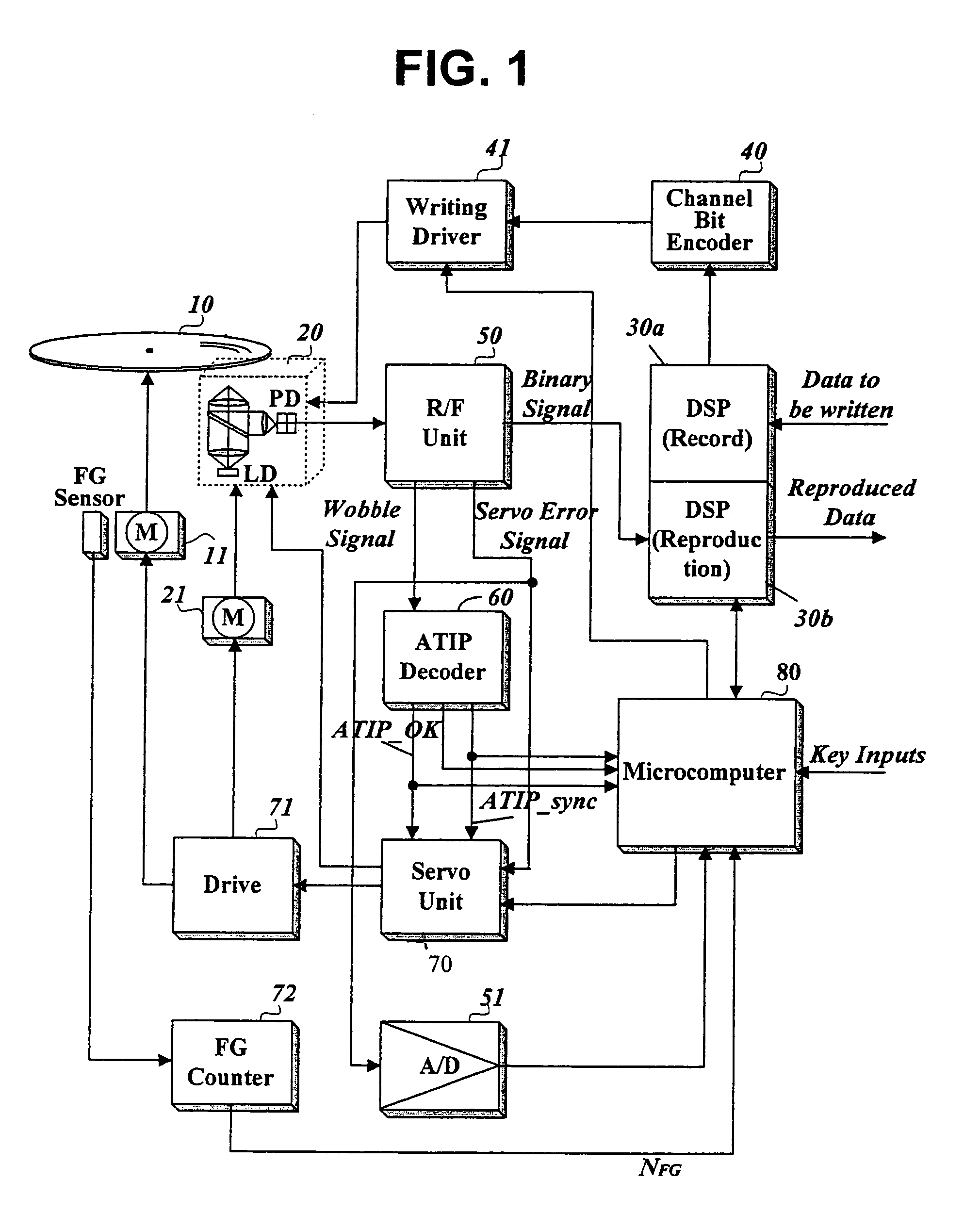
[0020]FIG. 1 is a block diagram of a disk drive which a method of detecting a defect area of a writable disk in accordance with the present invention is embedded in.

[0021]The disk drive of FIG. 1 comprises a digital recording signal processor 30a for converting input data into recording-formatted data as adding additional data such as an error correction code (ECC); a channel bit encoder 40 for converting the recording-formatted data into a PWM (Pulse Width Modulation) signal; a writing driver 41 for yielding a writing current according to the PWM signal; an optical pickup 20 for writing signals corresponding to the writing current onto a writable disk 10 and reproducing written signals from the writable disk 10; an R / F unit 50 for yielding servo error signals TE and FE (Focusing Error) and binary data signals through combining t...


PUM


Abstract

The present invention relates to a method of detecting a defect area without any mistake during data recording on a writable disk. This method detects a level of a servo error signal produced during a recording operation, checks whether the servo error signal is in an abnormal state based on the detected level, detects a periodic wobble signal or periodicity of the abnormal state occurrences of the servo error signal produced during the recording operation, and determines whether a recording area is in defect based on successful decoding of the detected periodic wobble signal or the periodicity of the abnormal state occurrences if the servo error signal is in an abnormal state. This method ensures exact detection of a defect area, whereby unnecessary speed reduction can be eliminated and successful data writing can be also guaranteed even in a defect area.

Description

BACKGROUND OF THE INVENTION[0001]1. Field of the Invention[0002]The present invention relates to a method of detecting a defect area of a disk without mistakes during data recording on a writable disk.[0003]2. Description of the Related Art[0004]A physical damage such as scratch etc. has an effect on a few or some physical tracks. Especially, a center area of a defect zone has the worst effect on data recording.[0005]If a high-speed data writing is tried at a center area of such a defect zone, a tracking servo control might be terminated so that a recording operation would be interrupted abruptly. In the case that a recording operation is abnormally ended, it is impossible to resume data recording from the abnormally-ended recording position, therefore, data recording must be re-started from the beginning inevitably. However, because a once-writable disk, namely, a CD-R can not be rewritable, it is obliged to be thrown away.[0006]For resolving this problem, various methods are being...

Claims


Application Information

Patent Timeline
IPC IPC(8): G11B7/095G11B20/18G11B27/19G11B27/24G11B27/36
CPCG11B20/18G11B27/36G11B27/19G11B2220/2545G11B2220/218G11B27/24
Inventor CHOI, YOUNG DOBANG, KEUK YOUNGJIN, CHEOL
Owner HITACHI LG DATA STORAGE KOREA
Learn More