
Read/write head with dynamic flying height control by magnetostriction

Inactive Publication Date: 2010-02-09
WESTERN DIGITAL TECH INC
View PDF61 Cites 164 Cited by
  • Summary
  • Abstract
  • Description
  • Claims
  • Application Information

AI Technical Summary

Benefits of technology

[0018]According to yet another embodiment, the magnetic coil provides a resistance heating for additional control of the dynamic flying height in addition to the magnetostriction effect.

Problems solved by technology

A significant design challenge in a conventional read / write head is to achieve an ultra low flying height without causing physical damage to either the slider or the disk that may result in reliability problems and head crashes.
Such as damage could cause both accelerated wear and performance degradation.
The wear effect is due to the abrasive contact between the slider and the disk, which tends to cause the slider off track, thereby causing errors in the track following capability of the read / write head.
Typically, during operation, the magnetic read / write head is subjected to various mechanical and thermal conditions that tend to compromise the ability to attain the ultra low flying height in a conventional read / write head.
Similarly, mechanical disturbances during operation, such as vibration, also pose as a source of difficulty in maintaining the ultra low flying height.
This rapid rotation is a source of friction in the ambient air between the ABS and the spinning magnetic disk, causing an elevation in the operation temperature of the read / write head.
The power dissipation manifests itself as a localized heating of the read / write head, resulting in a further temperature rise of the read / write head.
The combined mechanical and thermal effect therefore generally render the pole tip of the read / write head in a very close proximity to the magnetic disk in an uncontrolled manner that may possibly cause a physical interference of the read / write head.
Although this technology may have proven to be useful in controlling the dynamic flying height of the read / write head, it is still not entirely satisfactory in practice.
Due to the reliance on the thermal expansion effect as a means to control the dynamic flying height, the response time is relatively slow.
Since the ultra low flying height is typically lower than 12.5 nm, a flying height that is lower than 10 nm could cause a reliability problem.
The need for such a design has heretofore remained unsatisfied.

Method used


Image

  • Read/write head with dynamic flying height control by magnetostriction
  • Read/write head with dynamic flying height control by magnetostriction
  • Read/write head with dynamic flying height control by magnetostriction

Examples


Embodiment Construction

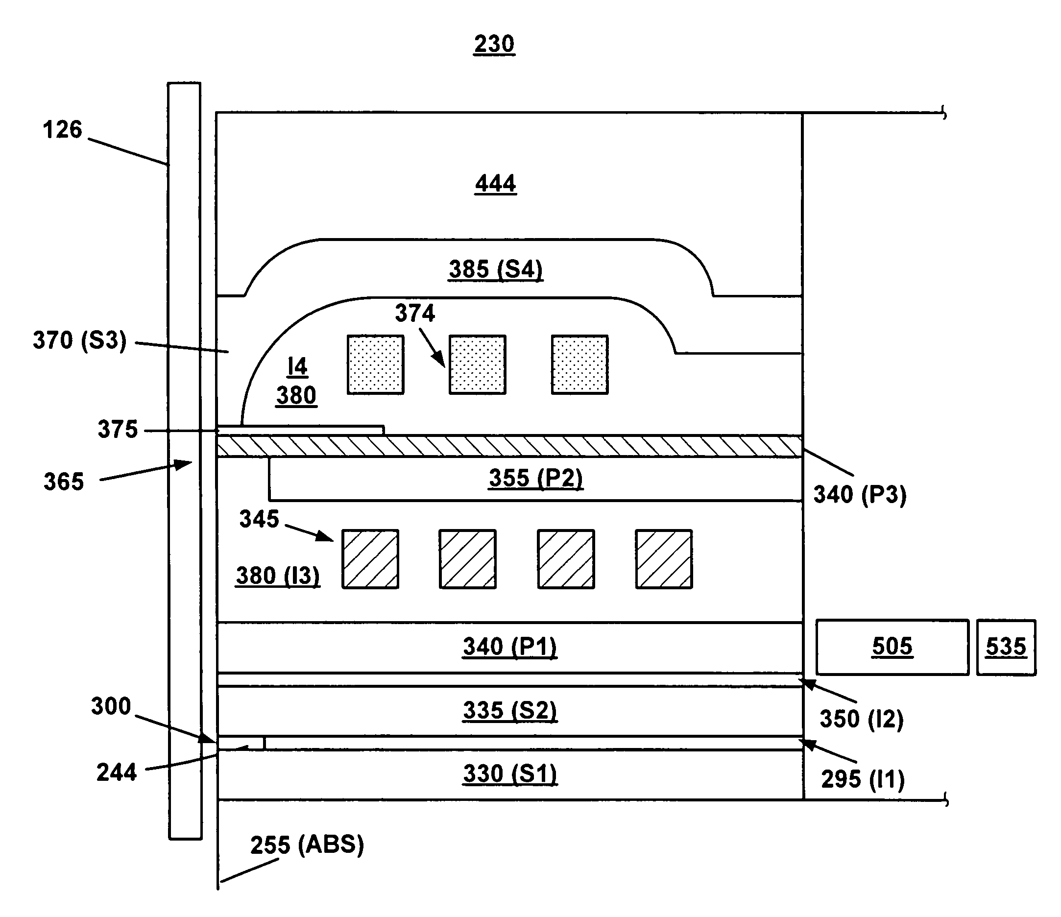
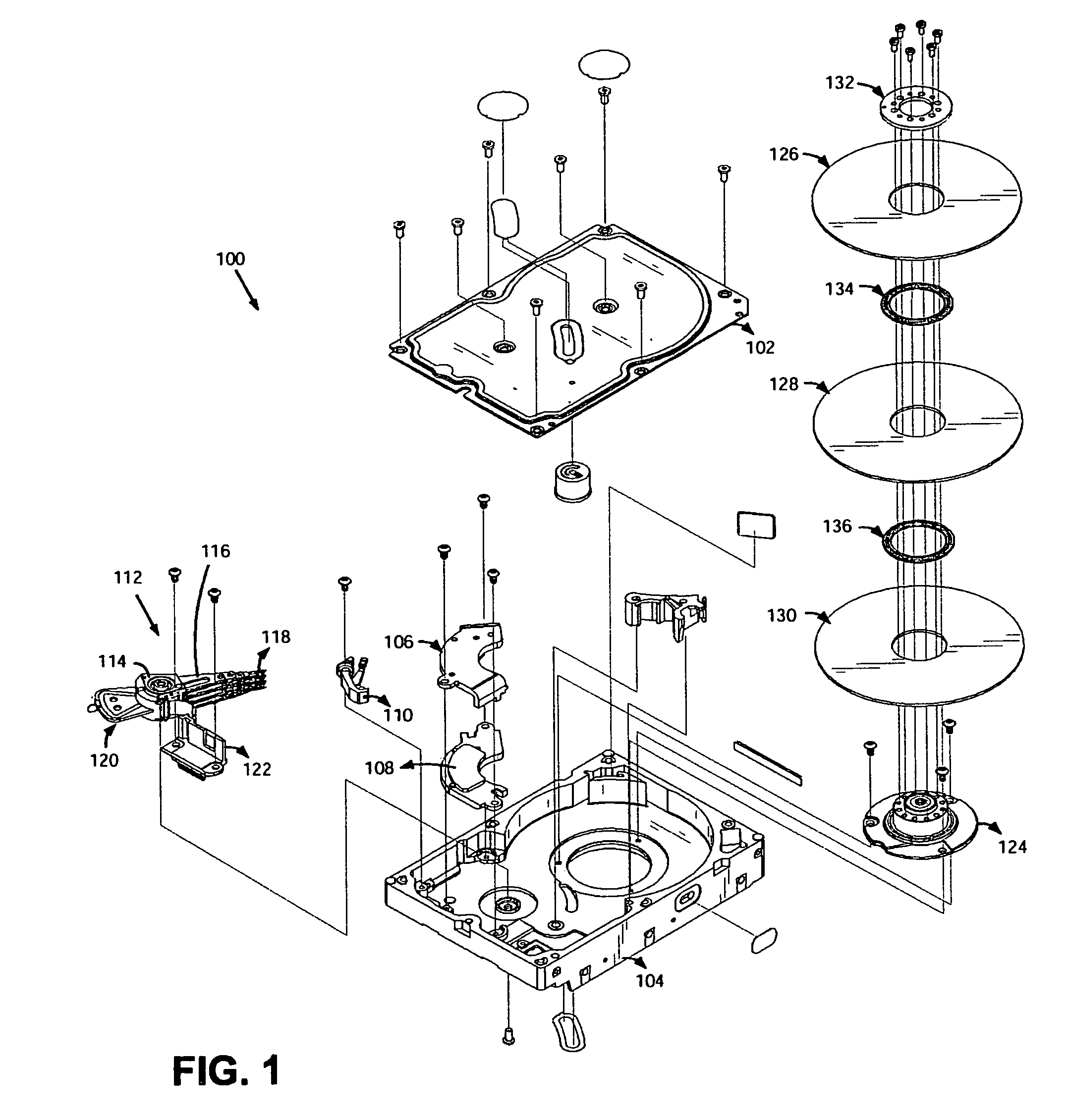
[0029]FIG. 1 illustrates a hard disk drive 100 in which an embodiment of the present invention may be used. An enclosure of the hard disk drive 100 comprises a cover 102 and a base 104. The enclosure is suitably sealed to provide a relatively contaminant-free interior for a head disk assembly (HDA) portion of the hard disk drive 100. The hard disk drive 100 also comprises a printed circuit board assembly (not shown) that is attached to base 104 and further comprises the circuitry for processing signals and controlling operations of the hard disk drive 100.

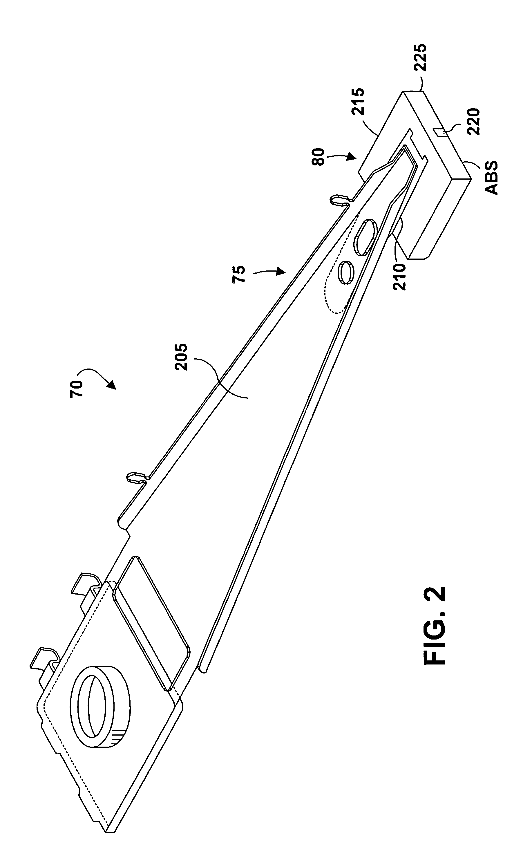
[0030]Within its interior, the hard disk drive 100 comprises a magnetic disk 126 having a recording surface typically on each side of the disk, and comprises a magnetic head or slider that may suitably be a magneto-resistive (“MR”) head such as a GMR head. The GMR head has an MR element for reading stored data on a recording surface and an inductive element for writing data on the recording surface. The exemplary embodiment of the ...


PUM


Abstract

A read / write head for use in a data storage device to control the low dynamic flying height in order to achieve high data recording storage capacity of magnetic hard drives. The read / write head is designed for use in a data storage device that includes a storage medium having a recording surface. The head comprises a pole tip region and an actuator. In turn, the actuator includes an excitation source for generating a magnetic field, and a magnetostrictive plate for expanding in response to the magnetic field, resulting in a protrusion in a section of the pole tip region along a direction towards the recording surface, so that the head flies above the recording surface at a flying height lower than a nominal flying height.

Description

FIELD OF THE INVENTION[0001]The present invention generally relates to data storage devices such as disk drives, and it particularly relates to a read / write head for use in such data storage devices. More specifically, the present invention provides a method of incorporating a new type of actuators comprising a magnetostrictive plate and magnetic excitation coils into the read / write head for dynamic flying height control during a read / write operation. The expansion of the magnetostrictive plate during actuation results in a reduction of the magnetic spacing between the read / write head and the magnetic medium to achieve higher data recording capacity of magnetic disks.BACKGROUND OF THE INVENTION[0002]An exemplary conventional read / write head comprises a thin film write element with a bottom pole P1 and a top pole P2. The pole P1 has a pole tip height dimension commonly referenced as “throat height”. In a finished write element, the throat height is measured between the ABS and a zero...

Claims


Application Information

Patent Timeline
IPC IPC(8): G11B5/56G11B21/24
CPCG11B5/3133G11B5/6005
Inventor LIU, FRANCIS H.STOEV, KROUM S.WANG, YUGANG
Owner WESTERN DIGITAL TECH INC
Learn More