Inductive write head having high magnetic moment poles and low magnetic moment thin layer in the back gap, and methods for making

a write head and high magnetic moment technology, applied in the field of methods, can solve the problems of high magnetic moment material corrosion, and high magnetic moment material exposed to atmosphere to quickly corrode, and achieve the effect of preventing corrosion

Inactive Publication Date: 2006-01-24
WESTERN DIGITAL TECH INC
View PDF28 Cites 147 Cited by
  • Summary
  • Abstract
  • Description
  • Claims
  • Application Information

AI Technical Summary

Benefits of technology

[0011]In addition to the first pole, the second pole can also be constructed of a high magnetic moment material, so that essentially the whole yoke is constructed of a high magnetic moment material. The relatively low magnetic moment capping layer can be formed of permalloy and advantageously prevents corrosion of the back gap of the first pole during fabrication of the rest of the write element. Although the capping layer is not constructed of a high magnetic moment material, it is sufficiently thin that it has a negligible effect on the magnetic performance of the write element. The capping layer is preferably on the order of 1000 Angstroms thick, but can range from 1000–3000 Angstroms in thickness, depending on the size of the back-gap. While the thickness of the capping layer can be varied it is preferably no more than 1 um thick.
[0013]A method for manufacturing such a write head includes first forming the first pole. The first pole is constructed of a high magnetic moment material, and the deposition process used to form the pole depends on the material chosen. For example high Fe content alloys such as NiFe55 can be plated whereas other high magnetic moment materials must be sputter deposited. Then, a photoresist material is spun and masked onto the first pole. The photoresist is then lifted off to expose the back gap, as well as a set of read element probing pads. Then a layer of permalloy is plated or sputtered onto the back gap. After that a magnetic coil is formed, preferably of copper, according to plating methods familiar to those skilled in the art. Another layer of photoresist is deposited and is cured using high temperatures to form smoothly rounded edges. The second pole is then plated so as to contact the thin layer of permalloy in the back gap portion of the first pole. Plating the back gap of the first pole with a thin layer of permalloy, advantageously prevents corrosion in the back gap which would otherwise occur due to the later wafer processes such as the high temperature cure of the second insulation layer, chemical etching, etc.

Problems solved by technology

However, use of such high magnetic moment material presents certain challenges.
For example, such high magnetic moment materials are highly corrosive.
This problem is compounded by the high temperatures required to cure the coil insulation layer 64 and by the wet processes required for wafer fabrication.
Such high temperatures cause any portion of high magnetic moment material exposed to atmosphere to quickly corrode.
Wet chemicals may react with high magnetic moment material and cause corrosion.

Method used


Image

  • Inductive write head having high magnetic moment poles and low magnetic moment thin layer in the back gap, and methods for making
  • Inductive write head having high magnetic moment poles and low magnetic moment thin layer in the back gap, and methods for making
  • Inductive write head having high magnetic moment poles and low magnetic moment thin layer in the back gap, and methods for making

Examples


Embodiment Construction

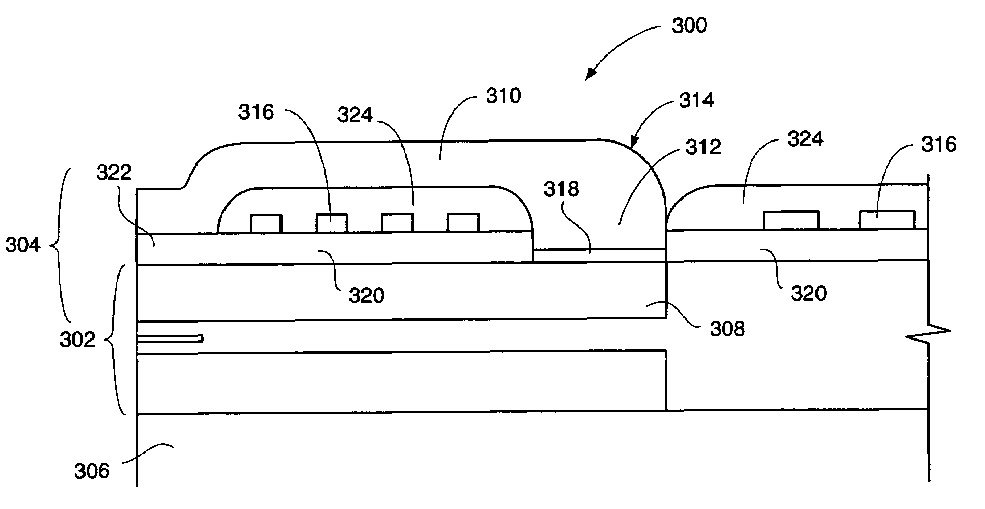
[0023]With reference to FIG. 3, the present invention is embodied in a merged read write head generally referred to as 300, including a read element 302 and write element 304, both of which are built upon a substrate 306 preferably constructed of ceramic. The read element 302 having been described with reference to the Background of the Invention, this Detailed Description will focus on the write element 304, which embodies the present invention. The write head includes a first pole 308 and a second pole 310, which meet at a back gap 312 to form a yoke 314. A coil 316 passes through the yoke 314 to induce a magnetic flux therein as previously discussed with reference to the Background of the Invention.

[0024]The first pole 308 is preferably constructed of a high magnetic moment (high Bsat) material, such as for example NiFe55, RhFeN and has a smooth upper surface generated by a chemical mechanical polishing process. A capping layer 318 constructed of relatively lower Bsat material co...


PUM

PropertyMeasurementUnit
thickaaaaaaaaaa
thickaaaaaaaaaa
writing currentaaaaaaaaaa

Abstract

The present invention provides a write element for use in magnetic data recording system such as a computer disk drive. The write head utilizes the advantageous properties of high magnetic moments while overcoming the corrosion problems engendered by such materials. The write element includes a magnetic yoke constructed of first and second magnetic poles joined to one another at a back gap. While the majority of the poles are constructed of a high magnetic moment material a layer of relatively low magnetic moment material is provided on the first pole at the back gap portion of the first pole. The relatively low magnetic moment material prevents corrosion of the first pole during subsequent manufacturing of the write head. An electrically conductive coil passes through the magnetic yoke and is insulated there from. By passing an electrical current through the electrical coil, a magnetic flux is generated in the yoke. This magnetic flux then generates a magnetic fringing field in at a write gap of the yoke. The fringing field imparts magnetic data onto a recording medium passing thereby.

Description

RELATED APPLICATIONS[0001]This application is a continuation of application Ser. No. 09 / 670, 413 filed 26 Sep. 2000, now abandoned.FIELD OF THE INVENTION[0002]The present invention relates to inductive write heads for use in magnetic data storage devices and more particularly to a method for manufacturing a write element having high magnetic moment poles.BACKGROUND OF THE INVENTION[0003]Magnetic disk drives are used to store and retrieve data for digital electronic apparatus such as computers. In FIGS. 1A and 1B, a magnetic disk data storage system 10 of the prior art includes a sealed enclosure 12, a disk drive motor 14, one or more magnetic disks 16, supported for rotation by a drive spindle 18 of motor 14, and an actuator 20 including at least one arm 22, the actuator being attached to a pivot bearing 24. Suspensions 26 are coupled to the ends of the arms 22, and each suspension supports at its distal end a read / write head or transducer 28. The head 28 (which will be described in...

Claims


Application Information

Patent Timeline
Patent Type & Authority Patents(United States)
IPC IPC(8): G11B5/127
CPCG11B5/31
Inventor DONG, ZI-WENWONG, JAMESBARR, RON
Owner WESTERN DIGITAL TECH INC
Why Eureka
Try Eureka