
Systems and methods for multi-dimensional enhancement using fictional border data

a fictional border and enhancement technology, applied in the field of multi-dimensional data processing, can solve the problems of loss, difficulty, loss, etc., in perceiving such low-contrast details, and the inability to control the illumination of video images, so as to improve image data, reduce the required processing overhead, and reduce the size of the kernel processing

Active Publication Date: 2006-08-15
Z MICROSYST
View PDF8 Cites 21 Cited by
  • Summary
  • Abstract
  • Description
  • Claims
  • Application Information

AI Technical Summary

Benefits of technology

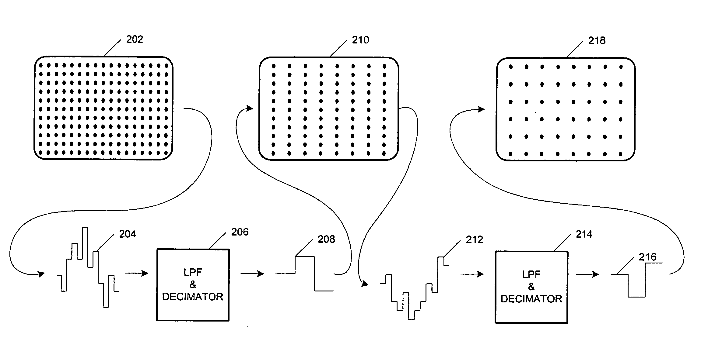
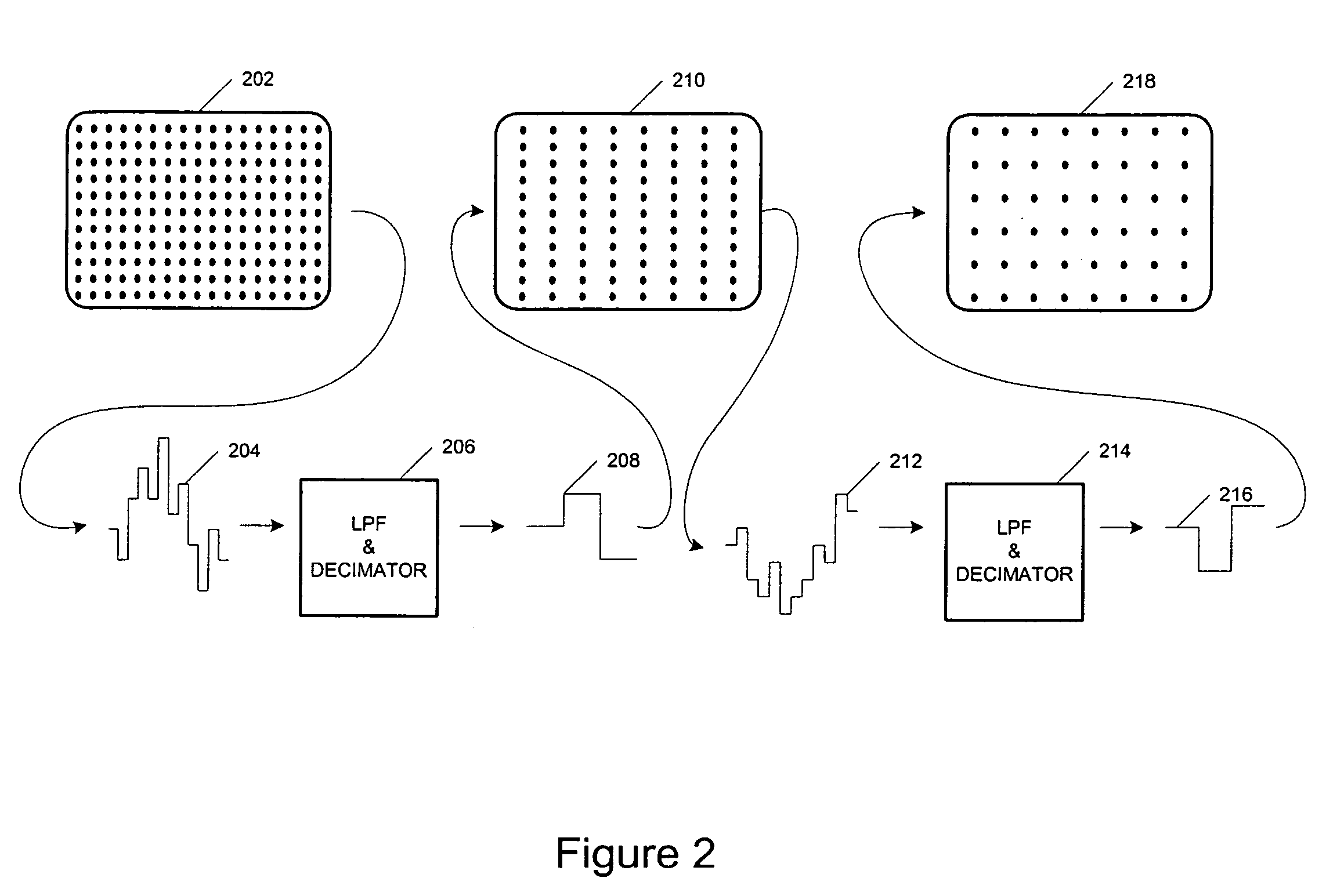
[0008]A multi-dimensional data enhancement system uses large kernel convolution techniques, in multi-dimensions, to improve image data in real-time. The multi-dimensional data enhancement system is capable of performing large kernel processing in real-time because the required processing overhead is significantly reduced. The reduction in processing overhead is achieved through the use of multi-dimensional filtering, decimation, and processing that reduces the amount of data that needs to be handled in certain stages of the operation, but still provides the same beneficial image enhancement.
[0009]In another aspect of the invention, the enhancement system can reduce the effect of pixels in surrounding image frames and the effect of blanking data on the processing of a pixel near the edge of an image frame by inserting fictional blanking data into the blanking areas.

Problems solved by technology

While there have been many advancements in video imaging technology, conventional video imaging systems can still suffer from deficiencies that impact the quality and usefulness of the video imagery produced.
For example, video images generated with uncontrolled illumination often contain important, but subtle, low-contrast details that can be obscured from the viewer's perception by large dynamic range variations in the image.
Any loss, or difficulty, in perceiving such low-contrast details can be detrimental in situations that require rapid responses to, or quick decisions based on, the images being presented.
The improvement that can be achieved using such small kernels, however, is often limited.
Unfortunately, the processing overhead required to perform large kernel convolution, in real-time, using conventional techniques, is prohibitive at the present state of digital signal processing technology.

Method used


Image

  • Systems and methods for multi-dimensional enhancement using fictional border data
  • Systems and methods for multi-dimensional enhancement using fictional border data
  • Systems and methods for multi-dimensional enhancement using fictional border data

Examples


Embodiment Construction

.”

BRIEF DESCRIPTION OF THE DRAWINGS

[0011]Features, aspects, and embodiments of the inventions are described in conjunction with the attached drawings, in which:

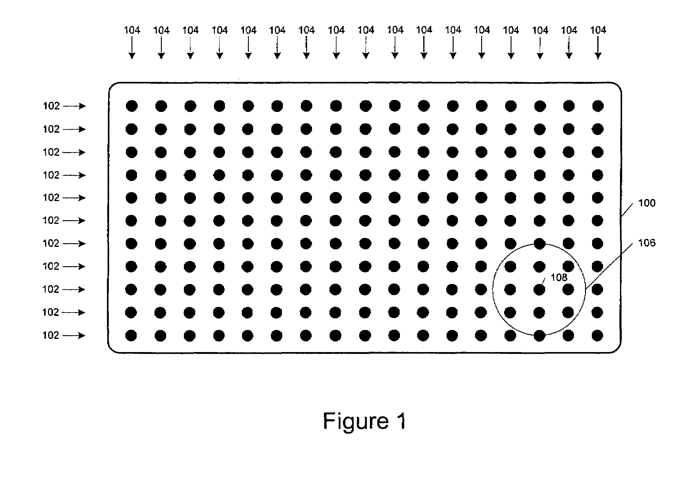
[0012]FIG. 1 is a diagram illustrating an exemplary display of image data;

[0013]FIG. 2 is a diagram illustrating filtering, and decimation of image data in accordance with one embodiment of the invention;

[0014]FIG. 3 is a diagram illustrating interpolation of the filtered and decimated image data of FIG. 2 in accordance with one embodiment of the invention;

[0015]FIG. 4 is a diagram illustrating a 3-dimensional image that can be the subject of filtering, decimation, and interpolation similar to that of FIGS. 2 and 3;

[0016]FIG. 5 is a diagram illustrating an example circuit for filtering and decimating image data in one dimension in accordance with one embodiment of the systems and methods described herein;

[0017]FIG. 6 is a diagram illustrating an example circuit for filtering and decimating the image data of FIG. 5 in a second...


PUM


Abstract

A multi-dimensional image data enhancement system is configured to reduce the effect of blanking areas on the large kernel processing of pixel data. Thus, when pixels comprising blanking data are processed, additional blanking data can be added to the blanking data such that the additional “fictional blanking data” will occupy an area within the kernel size instead of image data in an adjacent frame or non-related areas of the current frame.

Description

RELATED APPLICATION INFORMATION[0001]This application claims priority under 35 USC §119 to U.S. Provisional Patent Application 60 / 424,472, entitled “Multi-Dimensional Filtering, Decimation, and Processing of data Sets and Images,” filed Nov. 6, 2002, and to U.S. Provisional Patent Application 60 / 424,473, entitled “Large Kernel Processing of Pixels Near Edges of Data Frames With Additional Artificial Border Data by Processing the Border Data at a Higher Rate,” filed Nov. 6, 2002, both of which are incorporated herein in their entirety as if set forth in full.BACKGROUND[0002]1. Field of the Invention[0003]The present invention relates to multi-dimensional data processing, and more particularly, to the enhancement of image data.[0004]2. Background Information[0005]Imaging systems play a varied and important role in many different applications. For example, medical imaging applications, such as endoscopy, fluoroscopy, X-ray, arthroscopy, and microsurgery applications are helping to save...

Claims


Application Information

Patent Timeline
IPC IPC(8): G06K9/64G06T3/40G06T5/00G06T5/20G09G5/10
CPCG06T3/4007G06T3/4023G06T5/20G06T5/004G06T3/403G06T5/75G06T3/40G06T5/00
Inventor HIER, RICHARD G.COLEMAN, TERRENCE J.
Owner Z MICROSYST
Learn More