
Face modification tool

a technology of face modification and tool, applied in the field of three-dimensional modeling system, can solve the problems of complex, time-consuming, difficult to learn how to use, and high cost of csg application programs, and achieve the effect of avoiding adding new operations

Active Publication Date: 2006-08-15
AUTODESK INC
View PDF5 Cites 13 Cited by
  • Summary
  • Abstract
  • Description
  • Claims
  • Application Information

AI Technical Summary

Benefits of technology

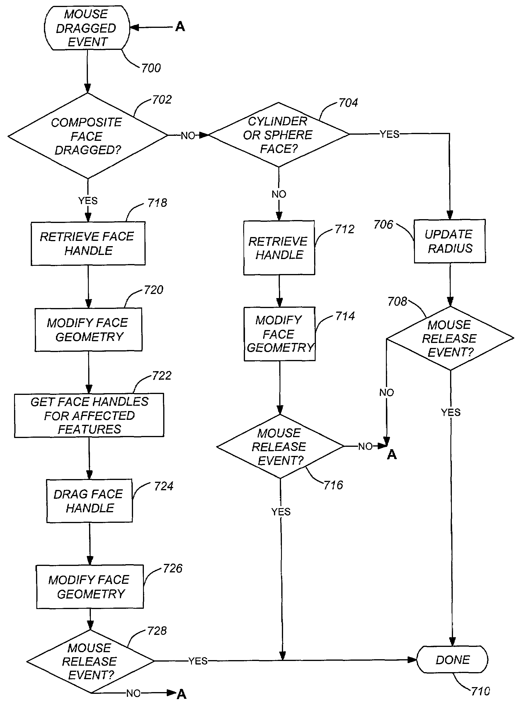
[0016]A face modification tool in accordance with one or more embodiments of the invention allows repositioning of a model's faces directly without any of the aforementioned side effects. The tool can modify the face of simple primitives directly, without the need to individually edit parameters. The tool also modifies faces with holes or complex faces by modifying the individual features simultaneously in such a way as to satisfy user expectation.

Problems solved by technology

CSG application programs ate often expensive, complex, and difficult to learn how to use.
Such modifications are time consuming and require the performance of multiple actions by a user.
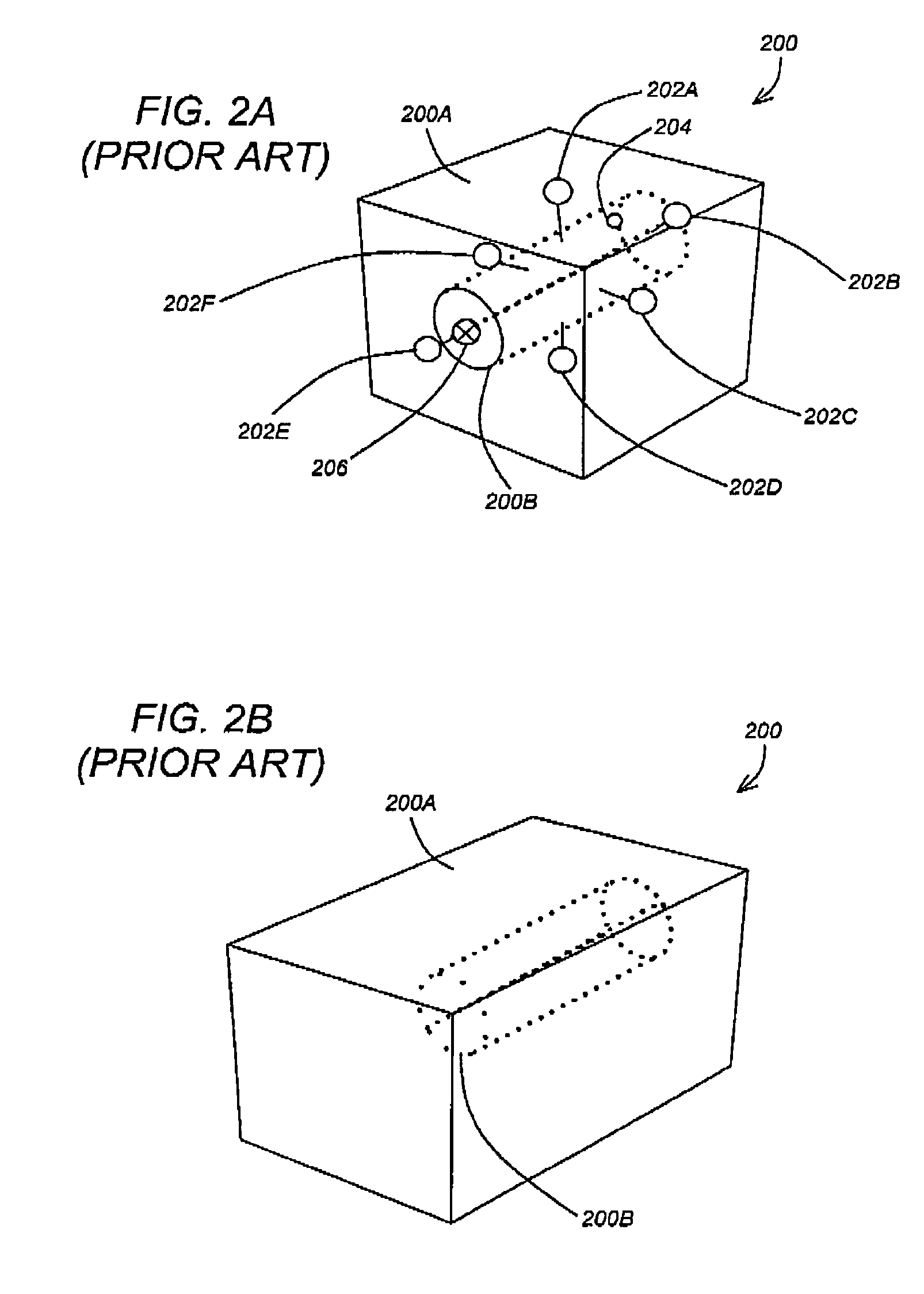
However, when the boundary representation of the model is changed directly, either the entire model is converted to a simple boundary representation (thereby discarding the knowledge of the primitives that were originally used to create the model), losing the procedural CSG history and thus the ability / advantages to modifying the model using feature parameters, or an additional operation is added to the procedural history.
Such a conversion and / or additional operation is time consuming, complicated, and adds unnecessary complications to the modification process.
Alternatively, the modifications to the geometry can be added as specific operations to the CSG history, but this introduces additional layers of complexity to subsequent interaction with the model.

Method used


Image

  • Face modification tool
  • Face modification tool
  • Face modification tool

Examples


Embodiment Construction

[0028]In the following description, reference is made to the accompanying drawings which form a part hereof, and which is shown, by way of illustration, several embodiments of the present invention. It is understood that other embodiments may be utilized and structural changes may be made without departing from the scope of the present invention.

Overview

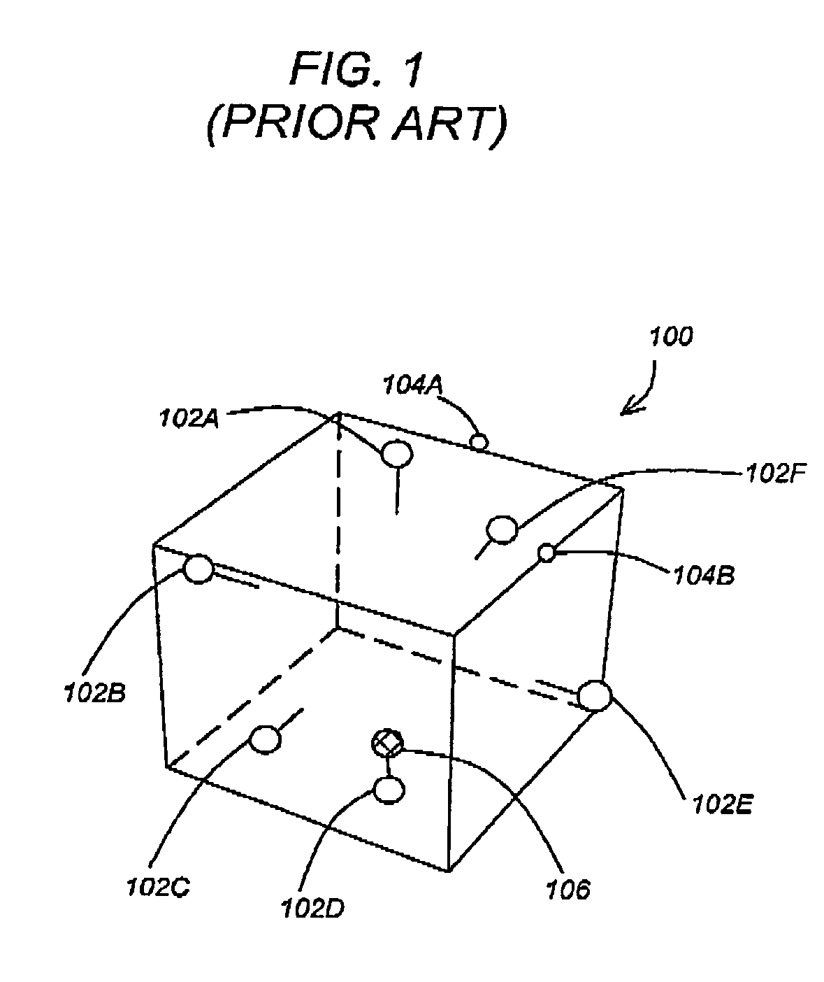
[0029]A model can be modified by changing the parameters of the individual features that make up the model or by changing the boundary representation of the model directly. Feature parameters include things like height, width, length, or radius. These parameters are typically modified by the user using dialogs or handles on a feature-by feature basis. When the boundary representation of a model is changed directly (i.e., not by modifying feature parameters), either the model is converted to a boundary representation or an additional operation is added to a procedural history for the CSG application.

[0030]In one or more embodiments of...


PUM


Abstract

One or more embodiments of the invention provide a method, apparatus, system, and article of manufacture for modifying a three-dimensional model. A composite three-dimensional model is displayed in a computer implemented solid modeling system. The composite model comprises a first primitive and a second primitive. A first face of the first primitive is selected. Once selected, a first boundary representation of the first primitive is modified using the selected first face. Thereafter, a second boundary representation of the second primitive is automatically modified based on the modification to the first boundary representation.

Description

CROSS-REFERENCE TO RELATED APPLICATIONS[0001]This application is related to the following co-pending and commonly-assigned patent application, which application is incorporated by reference herein:[0002]PCT Patent Application No. PCT / US01 / 02310, entitled “METHOD AND APPARATUS FOR PROVIDING ACCESS TO AND WORKING WITH ARCHITECTURAL DRAWINGS ON THE INTERNET”, by Douglas G. Look, et. al., filed on Jan. 24, 2001.BACKGROUND OF THE INVENTION[0003]1. Field of the Invention[0004]The present invention relates generally to a three-dimensional modeling system, and in particular, to a method, apparatus, and article of manufacture for directly repositioning a face of a three-dimensional model.[0005]2. Description of the Related Art[0006]The use of constructive solid geometry (CSG) application programs is well known in the art. CSG application programs ate often expensive, complex, and difficult to learn how to use. Three-dimensional (3D) models displayed in a CSG application are made up of one or...

Claims


Application Information

Patent Timeline
Patent Type & Authority Patents(United States)
IPC IPC(8): G06F7/60G06T17/00G06F3/033G06F3/048G06T17/10G06T17/40
CPCG06F3/04845G06T17/10G06T2219/2021G06T19/20G06F7/60
Inventor WANG, SHAMYERS, WILLIAM L.WALLACE, JOHN R.
Owner AUTODESK INC
Learn More