System, for matching harnesses of conductors with apertures in connectors

a technology of connectors and harnesses, applied in the field of complex wire harnesses, can solve problems such as unfavorable work positions, and achieve the effects of convenient use, easy maintenance, and easy learning

Active Publication Date: 2006-08-22
LOCKHEED MARTIN CORP
View PDF17 Cites 22 Cited by
  • Summary
  • Abstract
  • Description
  • Claims
  • Application Information

AI Technical Summary

Benefits of technology

[0011]The system can operate in very confined areas, is portable in nature, and is easily maintained. In addition, the system is easy to learn, easy to use, and virtually error free. In contrast, prior art systems are not so flexible, as they require much larger open areas (such as bench tops), and / or the attachment of a low voltage power source at the opposite end of the harness being pinned. The design of the present invention allows for it to be used by manufacturers or harness assemblers requiring much more remote and limited access, such as in the assembly of automobiles or aircraft.

Problems solved by technology

A technician moves to the pre-selected wire harness, which may be remote or difficult to access, where he or she will perform the wire pinning operation.
As illustrated in FIG. 3, this operation has a number of potentially high risk sources of error, including extremely small wire diameter, a large number of wires 21 per connector, close proximity of the wires in numerous harnesses 31, and limited work space 33, which creates awkward work positions.

Method used


Image

  • System, for matching harnesses of conductors with apertures in connectors
  • System, for matching harnesses of conductors with apertures in connectors
  • System, for matching harnesses of conductors with apertures in connectors

Examples


Embodiment Construction

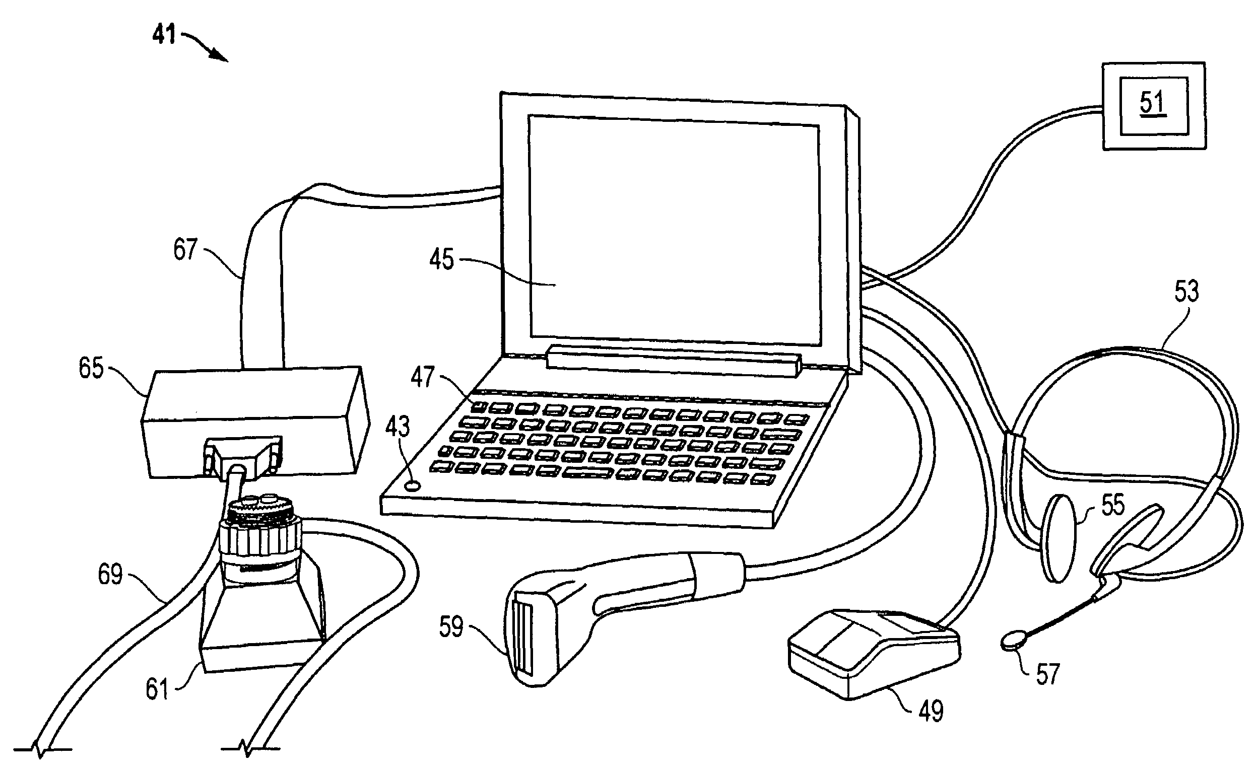
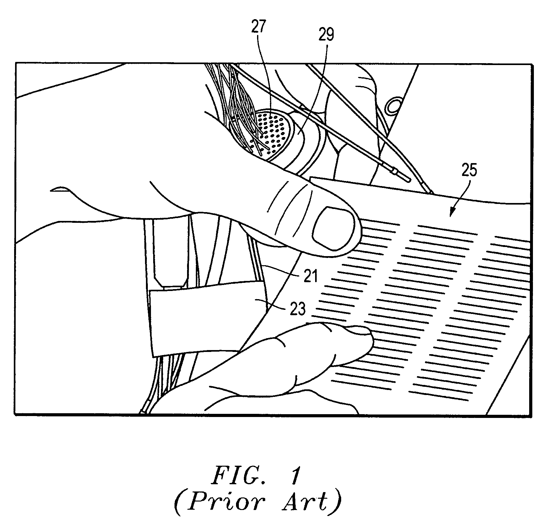
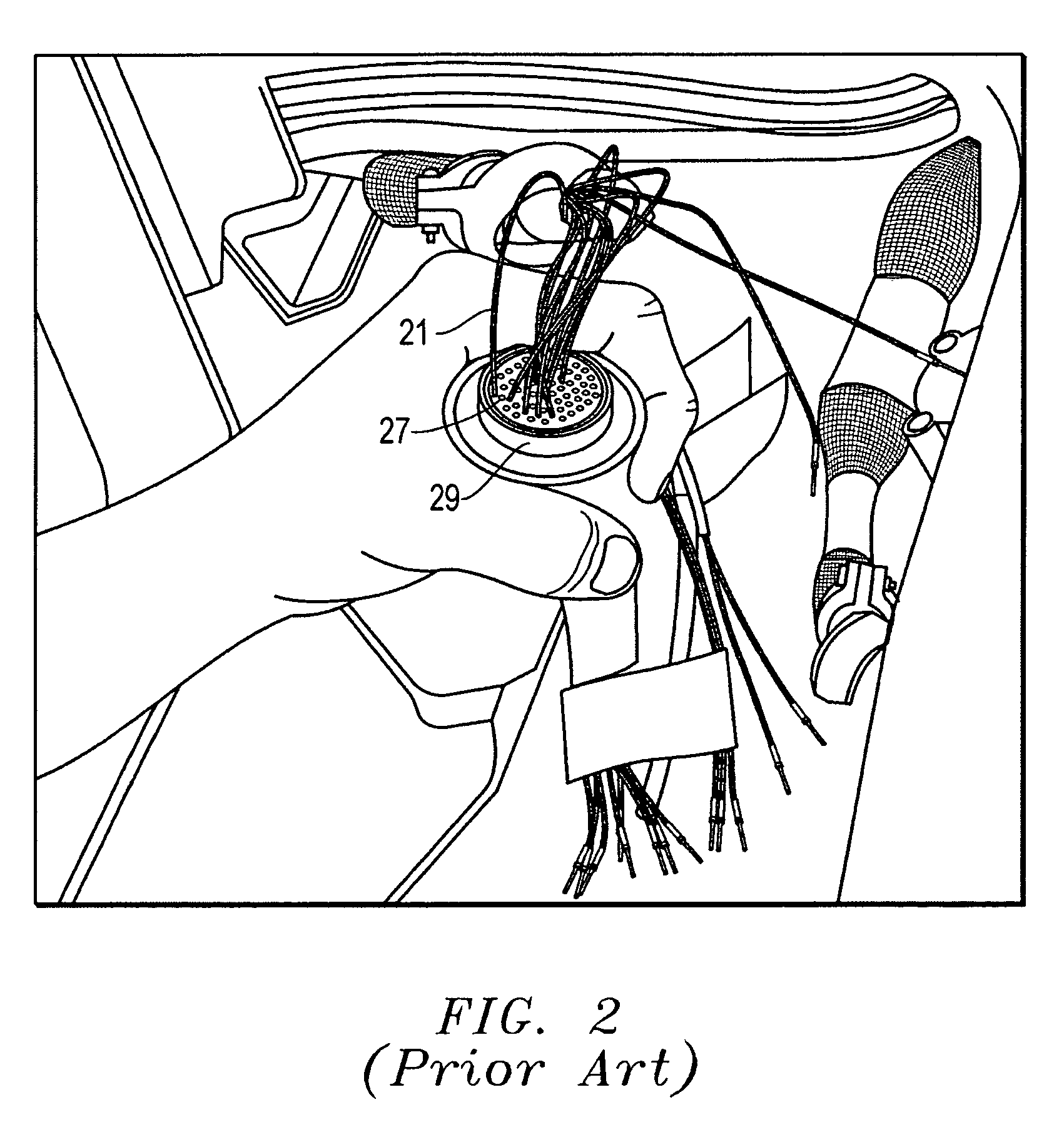
[0021]Referring to FIG. 4, one embodiment of a system 41, method, and apparatus for matching conductors with apertures in a connector is disclosed. The term “conductors” is used generically herein to refer to all types of conductors including but not limited to electrical and optical conductors, a single strand of wire, wires, and / or a cable of wires, etc. As described above and shown in the preceding FIGS. 1–3, the conductors 21 are usually bundled in groups or harnesses 31. A typical harness 31 may comprise only a few conductors 21 or more than 100 conductors 21. A typical connector 29 has many apertures 27 for receiving the terminal ends of the conductors 21.

[0022]The system 41 includes many different components, some of which are optional, as will be described below. Although many of these components are illustrated as being “hard-wired” to each other, they may utilize wireless technology as well. A main component of system 41 is a computer 43, such as the laptop computer shown....


PUM

PropertyMeasurementUnit
diametersaaaaaaaaaa
diameteraaaaaaaaaa
voltageaaaaaaaaaa

Abstract

A system for assembling wire harnesses with their connectors utilizes a compact computer-based system that is linked to an engineering data base. The data base contains component information, such as harness number, associated wires, and pin location to connector. An integrated tool contains a light panel that is linked to a dummy connector. The dummy connector has a mating end for the connector being pinned. The connector is mated to the dummy connector such that pin holes in the connector align with the light rods in the dummy connector. The wires are identified by voice recognition, bar code, and / or optical character recognition. Once a wire has been identified, the system illuminates the appropriate pin location on the selected connector, thereby providing a visible point of light in which the selected wire is to be terminated.

Description

BACKGROUND OF THE INVENTION[0001]1. Technical Field[0002]The present invention relates in general to assembling complex wire harnesses and, in particular, to an improved system, method, and apparatus for assembling wire harnesses with a connector light array designator.[0003]2. Description of the Related Art[0004]Many different industrial applications require the termination of large bundles or harnesses of wires into various types of connectors. In some applications, such as aircraft or automotive systems, each harness may contain more than 100 wires that must be routed and terminated in dozens of connectors throughout the assembly.[0005]In the prior art, current wire / connector matching and termination methods begin by printing engineering data that displays the wire numbers and their related pin locations in the connector. A technician moves to the pre-selected wire harness, which may be remote or difficult to access, where he or she will perform the wire pinning operation. Such p...

Claims


Application Information

Patent Timeline
Patent Type & Authority Patents(United States)
IPC IPC(8): B23P19/00G06F7/00B32B5/16B32B9/00B32B23/02
CPCH01R9/2475Y10T29/532Y10T29/5187Y10T428/2982Y10T29/53217Y10T29/53213Y10T29/49117H01R43/20
Inventor KELLEY, JAMES A.MALLECK, RICHARD A.LYONS, RICHARD G.
Owner LOCKHEED MARTIN CORP
Why Eureka
Try Eureka