Drilling device

a drilling device and drilling technology, applied in drilling machines and methods, surveys, constructions, etc., can solve the problem of pressure increase about the drilling device, and achieve the effect of avoiding the pressure increas

Inactive Publication Date: 2006-08-22
BADGER EXPLORER
View PDF18 Cites 16 Cited by
  • Summary
  • Abstract
  • Description
  • Claims
  • Application Information

AI Technical Summary

Benefits of technology

[0005]The objective of the invention is to bring into the earth's crust, in a relatively simple and inexpensive way, measuring equipment, to undertake measurements and to transmit measurement data to the user.

Problems solved by technology

Not being able to establish the same pre-drill degree of compaction of the drilled and ground up material, a pressure increase about the device must therefore be expected.

Method used


Image

  • Drilling device
  • Drilling device
  • Drilling device

Examples


Embodiment Construction

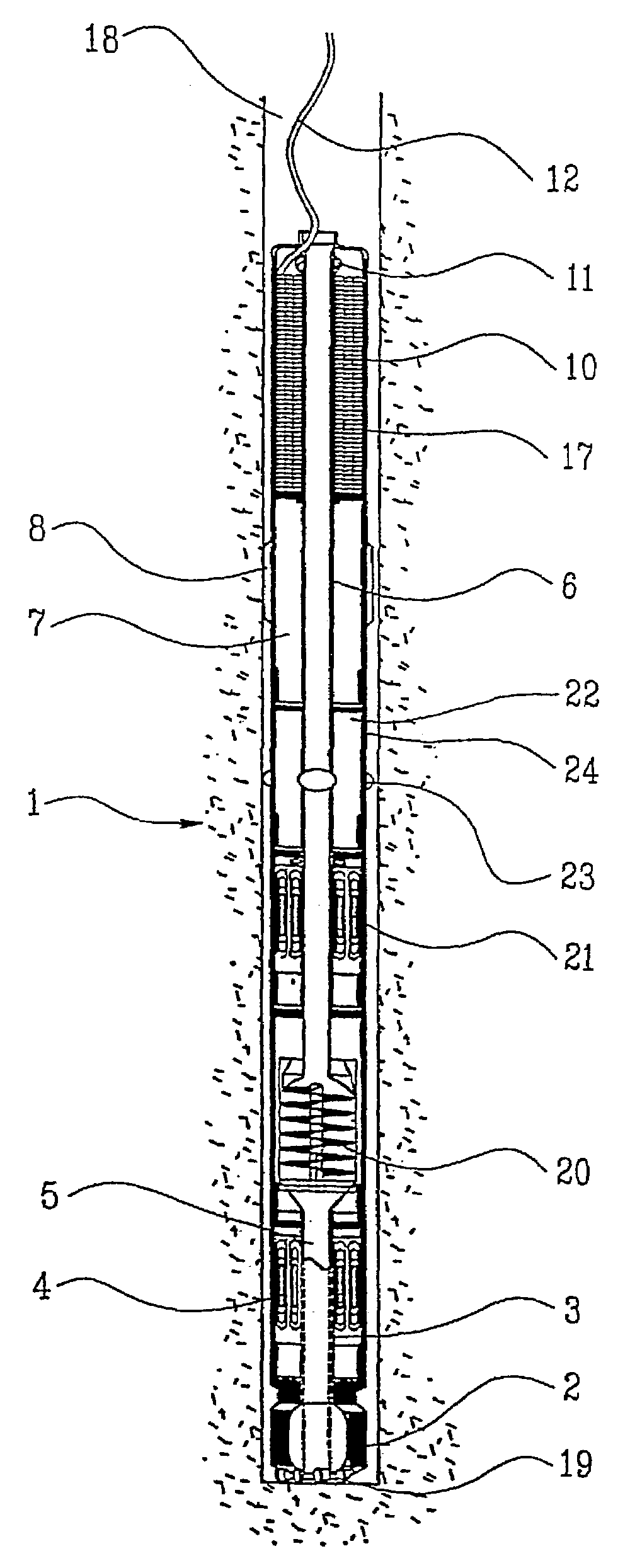
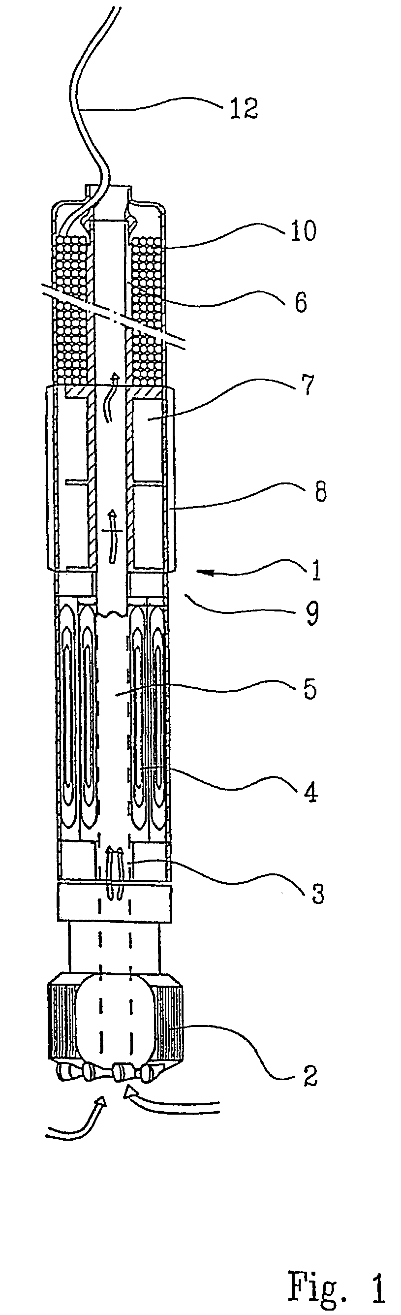
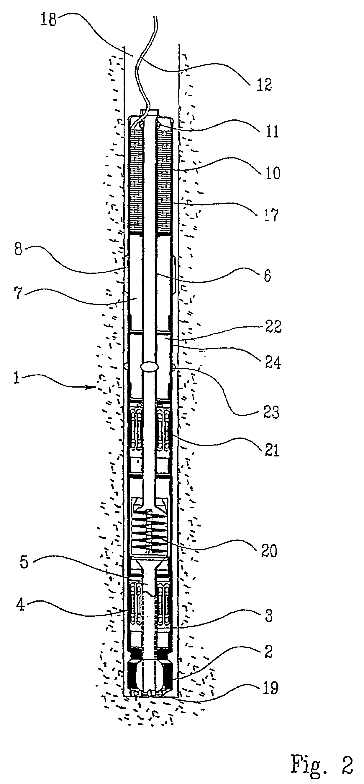
[0016]On the drawings, the reference numeral 1 denotes a drilling device comprising a drill bit 2 which, via a supported rotating and tubular central shaft 3, is connected to an electric driving motor 4. The through-going bore 5 of the central shaft 3 form the lower part of a through-going channel / tube 6 of the drilling device 1. Behind / above the driving motor 4, a steering component 7 is arranged. Besides forming a void for the placing of non-displayed electrical switching equipment and measuring- and communication instruments, the steering component 7 is provided with external, longitudinal and straight ribs 8. The intervention of the longitudinal and straight ribs 8 in a surrounding mass crushed by drilling and a formation 9, is arranged to dampen the rotary motion of the drilling device 1, which rotary motion is caused by the torque of the drill bit 2, thus reducing the resulting torque which initiates rotation of the drilling device 1. Behind / above the steering component 7, a m...


PUM


Abstract

Method of introducing instruments / measuring equipment / tools into formations (9) in the earth's crust or other solid materials, such as ice, by means of a drilling device (1), material being liberated by, for example, rotation of a drill bit (2), or by melting, for example by means of a heating element, the liberated material thereafter flowing, or being pumped, past / through the drilling device (1) and being deposited in the bore hole (18) above / behind the drilling device (1). A drilling device (1) for practising the method described above, comprising necessary components, for example a drill bit (2), a driving motor (4), and a steering / control component (7), the drilling device (1) being provided with a cable magazine (10) containing a cable (12), and possibly with an output feeder (11).

Description

CROSS REFERENCE TO RELATED APPLICATION[0001]The present application is the U.S. national stage application of International Application PCT / NO01 / 00270, filed Jun. 26, 2001, which international application was published on Feb. 21, 2002 as International Publication WO 02 / 14644. The International Application claims priority of Norwegian Patent Application 20003416, filed Jun. 29, 2000.SUMMARY OF THE INVENTION[0002]This invention concerns a method of subsurface investigations or investigation of ice, and a device for practicing the method, particularly to be applied when exploring for hydrocarbon or mineral occurrences.[0003]Exploring for oil and gas and the mapping of such resources is substantially limited by the cost associated with the drilling of exploration wells and delineation / step-out wells, and particularly for offshore projects. As the petroleum activity is moved into deeper waters, the cost of exploration, delineation and mapping increases. Large advances within the fields ...

Claims


Application Information

Patent Timeline
Patent Type & Authority Patents(United States)
IPC IPC(8): E21B7/02E21B7/00E21B47/12
CPCE21B47/122E21B7/008E21B23/14E21B47/13
Inventor STOKKA, SIGMUND
Owner BADGER EXPLORER
Why Eureka
Try Eureka